Dimension Loop Diagram
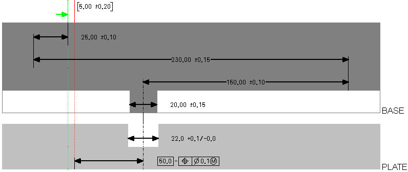
The Dimension Loop Diagramshows a 1-D loop diagram for the measurement. All of the dimensions and features of size are shown to scale in this diagram.
The measurement is shown at the top of the diagram. The location of the first measurement reference feature is represented by a vertical green line, and the location of the second reference feature is represented by a vertical red line.
Each part involved in the dimension loop is represented by a box in the dimension loop diagram. All of the features and dimensions that are related to a part are shown within the part box. The vertical line segments at the ends of the dimensions represent the standard features.
Interfaces are represented between the part boxes. For Pin/Hole interfaces, a Float attachment is shown with a double arrow, as shown in the below figure. For the other attachment options, a vertical line shows the location for the attachment, such as, Left, Right, or Center.
If you click a part box, a dimension line, or the measurement, the corresponding object is highlighted in the Measurement Definition table and in the Creo Parametric model.