Cementing Insulators
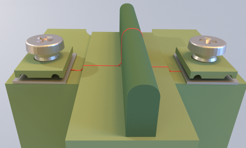
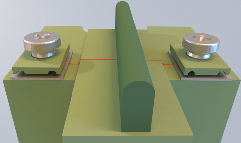
A current can flow through and around the touching and uncemented areas. The cementation or uncementation of adjacent insulating components impacts the clearance and creepage analysis results. The following images of cemented and uncemented components provides an example of this influence on the creepage path.
|
Cemented components
|
Uncemented components
|
|
|
|
|
 A partial specification of joints between two components is not currently supported, however there is a special treatment for cementations due to rivets. |
To Cement Components
1. Under Cemented Component Pairs, click Insert new cementation. The Select dialog box opens.
2. Select the component pair from the graphics window and click OK in the Select dialog box.
The selected components are cemented and appear under Cemented Component Pairs.
All joints between the components are automatically considered cemented.
To delete a cemented item, right-click and click Remove.
Excluding Components
You can explicitly exclude components from the analysis without deleting them from the assembly, by adding them under Excluded Components. The components added under Excluded Components are hidden in the graphics window. To unhide the components, remove them from the exclusion list.
Excluding flexible insulating components is recommended. For example, cables can extend a creepage and clearance path when they accidentally lie between two electric nets. Due to their flexibility, it is impossible to predict their exact position in the real assembly.


