Stock Boundary and Cut Extensions
The cut for Area and Groove turning is defined by specifying a stock outline and a turn profile, and by how the turn profile extends to intersect the stock outline. The result is a closed region representing the area of the cut.
The stock outline may be a workpiece or stock boundary. If you have not defined a workpiece, you can sketch a stock boundary by using options the Stock Boundary options for Area and Groove turning.
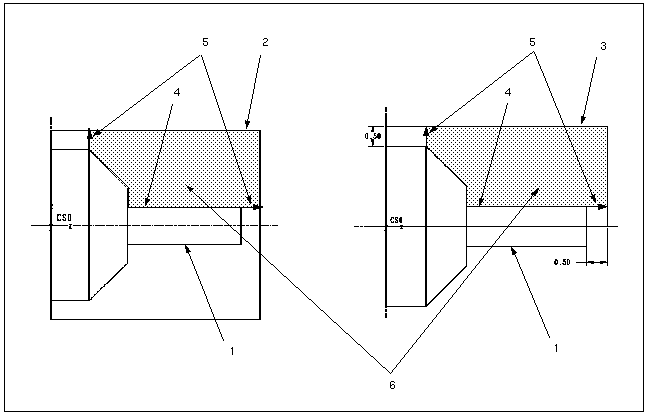
The graphic below illustrates how the cut area is determined. The schematic on the left shows a manufacturing model with one reference part and one workpiece, where the workpiece cross section is automatically used as stock boundary. In the schematic on the right, there is no workpiece, therefore, you have to sketch the stock boundary.
1. Reference part
2. Workpiece
3. Stock boundary sketch
4. Cut sketch
5. Cut extensions
6. Cut area
If your manufacturing model contains one workpiece, you can use a sketched stock boundary.
|  Since the area of the cut is determined using the workpiece cross section, it is recommended that you perform material removal for each NC sequence right after it is created, to avoid air machining in subsequent NC sequences. If you do not want to perform material removal, click Turn >  Stock Boundary Stock Boundary to sketch the new stock outline. |

