Creo Harness Manufacturing > Creo Harness Manufacturing > Planning and Modelling Considerations > HMX Customization (Advanced License only)
  
HMX Customization (Advanced License only)
You can use the customization options available for HMX to customize the Wire List, BOM and Cavity tables to show parameters from the Harness Manufacturing Extension dialog box.
Symbol Display
You can control the display of the symbols for item number balloons and component reference designators by setting the values for the following parameters to Show or Hide:
Balloons
Reference Designators
The default value is Show.
Segment Flaring
Cone angle is defined as the angular offset from the vertical branch to the first splayed branch.
 
* You can define a cone angle for branch ends with more than three splayed segments.
You can control the cone angle by setting the value of Cone Angle to a real number greater than 0. The value is interpreted as degrees. The default value is 0.
 
* The cone angle should be between 0 and 75 degrees.
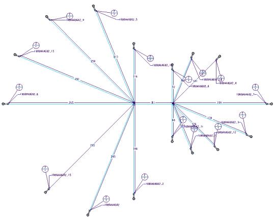
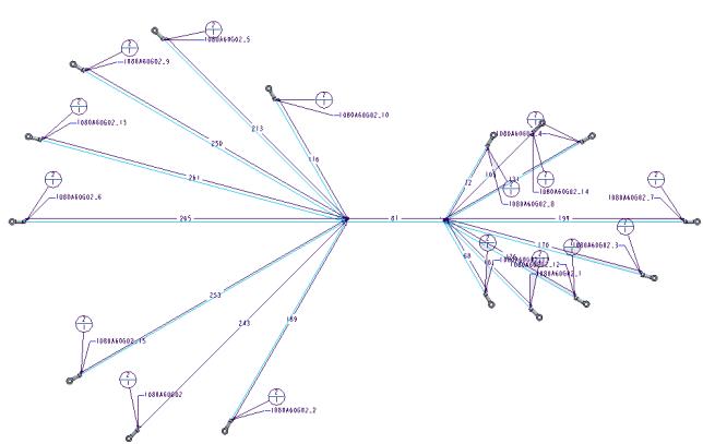
The following figures show the difference in the Harness Manufacturing drawing when the cone angle is change to 30 degrees.
Cone angle 0 degrees
Cone angle 30 degrees
Output File Creation
You can control the generation of output file produced by HMX by setting the values of the following key parameters to Yes or No:
Key Parameter Name
Description
Default value
Log File
Controls the creation of log files.
No
BoM File
Controls the creations of BOM files.
Yes
Wire List file
Controls the creation of Wire List files.
Yes
Unique File Names
Controls the names of the created files.
No
Length Inflation
You can control the output values of the extracted wire or cable lengths reported in the Wire List and BOM. These values are not in the generated stick drawing.
Key Parameter Name
Description
Default value
Example
Extra Length (%)
Increases the value of the wire lengths displayed in the Wire List and BOM tables by the specified percentage.
Type a value that is a real number restricted to 3 decimals.
0
Extra Length (%) : 5.125
Fixed Length
Increases the value of the wire lengths displayed in the Wire List and BOM tables by the specified length.
Specify a whole number for metric or a real number to one decimal for inches. The units specified for Fixed Length must match the spools units.
 
If the units are in millimeters, and a real number is entered, the value of the wire length is rounded off to the nearest integer. For example, if you type 10.5 as the additional fixed length of the wire, then the value changes to 10.
If the units are in inches, the value is restricted to real numbers with a single decimal place. For example, if you type 10.55, then the value changes to 10.5.
If Fixed Length and Extra Length (%) are specified, the value of Fixed Length is used for calculating the change in the wire length.
0
Fixed Length : 5(mm) or 0.1 (inches)
Round to Length
Rounds up the value of the wire length displayed in the Wire List and associated spool in the BOM table by the specified length. Specify a whole number for metric or a real number that can have up to one decimal for inches.
 
If the units are in millimeters, the value of the wire length is rounded down to the nearest integer. For example, if you type 10.5 as the rounded to length of the wire, then the value changes to 10.
By default, the round off additional value entered for the wire length is rounded up to the nearest integer only when the units are in millimeters for harnesses, not when the units are in inches.
0
Round to length : 5(mm) or 0.5 (inches)
Include Shields in Wire List
Controls the listing of shields in the Wire List table. If you select Yes, the shields that are fully routed appear in the generated Wire List table.
Yes
Example: Change Wire Length
Refer the multiple_markers.asm sample assembly to learn how to increase the wire lengths by a specific percentage. Sample models are available at <Creo load point>\Common Files\help\sample_models\hmx\Key_parameters. Open the multiple_markers.asm sample assembly.
1. Click Applications > Harness Mfg. The Harness Manufacturing Extension dialog box opens.
 
* You may have to change the value of the configuration option pro_unit_length to mm.
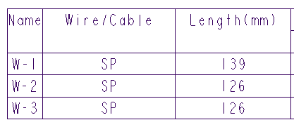
2. Click Flatten Harness to generate the harness drawing for the sample assembly. The following image shows the wire lengths when Extra Length (%) is set to the default value.
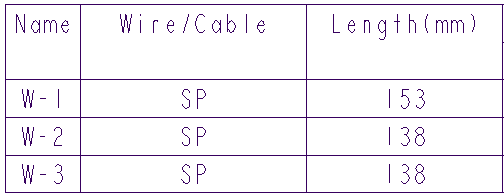
3. Edit the Extra Length (%) to 10.
4. Click Flatten Harness to re-create the harness drawing. Note that the wire lengths have increased by 10 percent.
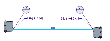
The following image shows the drawing output with updated wire lengths.
Connector Placement - Dimension To Front
You can set the dimensioning scheme to be front of the connectors or rear of connectors by setting the value of the parameter DimensionTo Front to Yes or No. The default value is No. The dimension placed on the segment leading to the connector stops at the end of the connector and does not include the connector length.
Dimension to Front is set to No
Dimension to Front is set to Yes
Connector Centralization
You can centralize connectors on the graphic harness manufacturing drawing output or maintain the connector visualization to the shortest routed wire by setting the value of the parameter Centralize Connectors to Yes or No. The default value is Yes. The connector will be attached to the sketch from a pin that is in the centre of all the routed pins. If the value is set to No, the connectors are attached to the sketch by the pin corresponding to the wire of the shortest length routed to the connector.
The following figures show the difference in the harness manufacturing drawings with different Centralize Connectors values.
Shortest wire view
Centralised View
Cavity Table Pin Display
Display Empty Pins
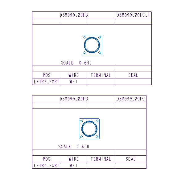
The Connector Cavity table lists all pins in the associated connector. You can control the listing of all cavities in the output Cavity table using the Display Empty Pins option. The Display Empty Pins option is set to Yes by default.
If the Display Empty Pins option is set to No, the pins that do not have an extracted parameter value e.g. term_name are not shown in the Cavity table for the connector.
Empty pins not displayed
Empty pins displayed