MCAD to ECAD Workflow
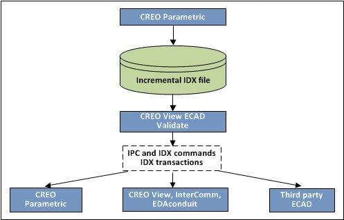
The following figure shows the sequence of the collaboration effort beginning in Creo Parametric.
The MCAD user performs the following tasks:
1. Creates a new ECAD assembly design and assembles a board part.
2. Adds mounting holes and ECAD areas, but does not add mechanical parts. Although the mechanical components such as switches and connectors are normally controlled by the MCAD user, asking the ECAD user to place them ensures that the reference designators are aligned electronically. Placement of these components does not have to be exact. They are placed correctly in Creo Parametric.
3. Saves the ECAD assembly design as a baseline EDMD IDX file.
4. Sends the EDMD IDX file to the ECAD user.
The ECAD user receives the baseline EDMD IDX file sent by the Creo Parametric user and performs the following steps:
1. Imports the EDMD IDX file with the board outline into a native ECAD tool.
2. Places mechanical components in the design. When the ECAD user places the components they are added with the correct reference designators. The MCAD user does not have to manually add the ECAD_NAME and ECAD_ALT_NAME parameter on each component.
3. Saves a second baseline EDMD *.idx file of the modified design and sends it to the Creo Parametric user.
The ECAD and MCAD users agree on a baseline EDMD IDX file to begin the design process.
The MCAD user develops the design:
1. The MCAD user saves this design as an EDA file to use as the first compare-to-design.
2. The MCAD user develops the design. This can include the addition, deletion, modification, and movement of assembly components or board outline changes.
3. When he finishes, the MCAD user saves the design as an EDA file. This is now the current design.
4. With the assembly design open in
Creo Parametric, the MCAD user clicks
Applications >
 ECAD Collaboration
 to enter
Creo ECAD-MCAD Collaboration.
|  He can also open the last version of the design from which he would like to track changes. |
5. The MCAD user clicks
 Compare
 and selects the compare-to-design
*.eda file.
Creo View ECAD Compare displays the comparison results.
|  The changed data includes board outline changes and the added, deleted, moved, and modified components of the ECAD assembly. These parametric variations in data are the proposed changes. |
6. The MCAD user clicks File > Save As in Creo View ECAD Validate to generate an incremental EDMD IDX file with the proposed design changes.
7. The MCAD user sends the incremental EDMD IDX file with the proposed changes to the ECAD user.
The ECAD user receives the Incremental EDMD IDX file and performs the following tasks in ECAD:
1. Opens the EDMD IDX file received from the Creo Parametric user in Creo View ECAD Validate.
2. Verifies the changes proposed by the Creo Parametric user.
3. Accepts all the proposed changes or rejects some of them, proposes additional changes if any, and saves the changes to the ECAD file and the incremental EDMD IDX file.
4. The ECAD user sends the updated incremental EDMD IDX file to the Creo Parametric user.
5. The Creo Parametric user analyzes the rejected proposals and additional proposals in Creo View ECAD Validate and updates the design in Creo Parametric.
6. The MCAD user saves the updated design as a new compare-to-design.
7. The MCAD user accepts or rejects the proposed changes and updates the EDMD IDX file.
8. The MCAD user then sends this updated EDMD IDX file to the ECAD user.
9. The exchange continues until the designs are synchronized and a new EDMD IDX baseline file is created.


 ECAD Collaboration to enter Creo ECAD-MCAD Collaboration.
 Compare and selects the compare-to-design *.eda file. Creo View ECAD Compare displays the comparison results.