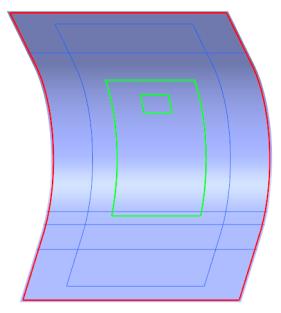
Create a Core Ply (CORE_1)
1. Click  Core. The Core tab opens.
Core. The Core tab opens.2. Under Type, make sure that  Manual Core is selected.
Manual Core is selected.3. Define the boundary chains as follows:
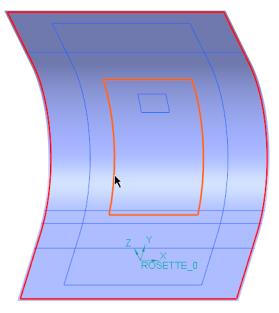
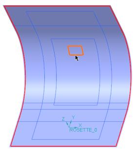
a. For Loop 1, select the boundary chain CompCrv:F12(CURVE), as shown in the following graphic:
b. Click Add Loop.
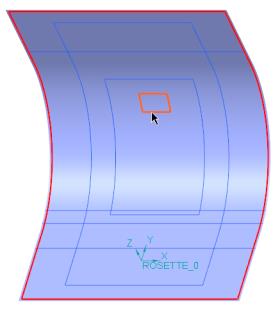
c. For Loop 2, select the boundary chain CompCrv:F13(CURVE), as shown in the following graphic:
4. In the Material box, select AIREX-C70_130.
5. Click the Taper tab.
6. Define the taper chains as follows:
a. For Set 1, select the taper chain CompCrv:F12(CURVE), as shown in the following graphic:
b. For Set 1, define the taper dimensions as follows:
a. In the D1 box, type 15, and press Enter.
b. In the D2 box, type 0, and press Enter.

c. Click New set.
d. For Set 2, select the taper chain CompCrv:F13(CURVE), as shown in the following graphic:
e. For Set 2, define the taper dimensions as follows:
a. In the D1 box, type 15, and press Enter.
b. In the D2 box, type 0, and press Enter.
7. Click  OK. A core ply (CORE_1) is created.
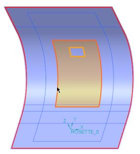
OK. A core ply (CORE_1) is created.8. Click in the empty space in the graphics window. The boundary of CORE_1 is highlighted, as shown in the following graphic: