Performing the Simulation
Click Common in the Flow Analysis Tree to change the settings for the simulation in the Properties panel. Simulations are of two types: steady state and transient. You can set the simulation type under Time Definition in the Properties panel.
• Steady State Simulation—Neglects the effects of time. Transient processes, like centrifugal impeller, are approximated as a time-averaged, steady state process using the moving reference frames. The following settings are available in the Properties panel when you set Time Definition to Steady State Simulation.
◦ Number of Iterations—Point at which the code stops (Steady) or moves to the next time step (Transient). Number of iterations should be sufficiently large to allow the Converge Criterion for all modules to be satisfied.
◦ Time Definition—Allows you to set the simulation as Steady State Simulation.
◦ Result Saving Frequency—Generates a results file Filename.sres when the run is completed. Depending on the value for Result Saving Frequency, the same result file is overwritten.
◦ Mesh Update Frequency(Iterations)—Determines the frequency (number of iterations) to update the mesh.
◦ Additional Output Files—Provides the options of No Other Outputs or an output in EnSight Format.
• Transient Simulation—Includes the effects of time. Examples of transient problems are those with time varying boundary conditions, moving parts, or instabilities, which can only be solved using the Transient option. The following settings are available in the Properties panel when you set Time Definition to Transient.
◦ Number of Iterations—Point at which the code stops (Steady) or moves to the next time step (Transient). Number of iterations should be sufficiently large to allow the Converge Criterion for all modules to be satisfied.
◦ Time Definition—Allows you to set the simulation as Transient and provides the following options:
▪ Simulation Time (Duration)—Duration, in seconds, of a transient simulation. The simulation time combined with the number of time steps determines the size of the time steps.
▪ Number of Time Steps
◦ Result Saving Frequency—Determines the frequency of the output of the results file .sres and controls the output frequency for Additional Output Files.
◦ Cycle Computation Interval—Determines the frequency (time steps) to update the mesh.
◦ Additional Output Files—Provides the options of No Other Outputs or an output in EnSight Format.
Running the Simulation
1. Click >  Flow Analysis.
Flow Analysis.2. Click  New Project and then click
  Run to start the simulation.
New Project and then click Run to start the simulation.3. Click  Pause or
  Stop to pause or stop the simulation.
Pause or Stop to pause or stop the simulation.The other options available in the Run group are listed below, as shown in the following figure:

Start from Initial Values | Enables the Start of a solution using initial values. Initial Values for each Module are set on a Volume by Volume basis. Begins the calculations from values specified as conditions at volumes or boundaries. |
Start from Solution | Enables the start of a Steady or Transient simulation using solution results from a previous simulation. Begins the calculations from an existing result. |
Steady | Performs the calculations neglecting the effects of time. |
Transient | Performs the calculations including the effects of time. |
Continuation Run | Enables the uninterrupted continuation of a Steady or Transient simulation, as if the simulation had never been stopped. |
Study Check | Study check is automatically performed before starting the simulation. It can be performed manually by clicking the Study Check icon. This feature checks if the following features are included in the simulation and notifies the user if any of these are missing. It also reports errors in simulation settings and simulation runtime errors. For example, a common error for multiphase simulations is when sum of volume fraction at a boundary or volume is not unity which will be detected during Study Check.• Physics Modules are enabled • Simulation Domains are added for simulation • Boundary and Volume conditions are set • Mesh is generated • Runtime errors |
Batch Run
Batch run is used to run simulation for multiple projects in sequence.
To use Batch Run, perform the following:
1. Click on  in the Run group in CFA ribbon. The Batch Run dialog box opens.
in the Run group in CFA ribbon. The Batch Run dialog box opens.2. Select the desired Projects from the list.
3. Click Run to start the Batch Run of the selected Projects.

Behavioral Modeling
Behavioral Modeling can be used to perform sensitivity analysis of geometric parameters on CFD output variables and optimization of geometric parameters with respect to the CFD output variables.
To link the CFD output parameters with Behavioral Modeling extension available in Creo, follow the following steps:
1. Follow the CFD workflow to set-up the simulation model using Creo Flow Analysis.
2. Select the boundaries or domains of interest and enable the output of desired variables required for the sensitivity or optimization analysis.
3. Click on the Behavioral Modeling in the Operations group of CFA Ribbon. The Behavioral Modeling properties dialog box opens.
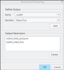
4. Select the desired boundary or domain under the Entity drop-down list.
5. Select the desired variable under the Variable drop-down list.
6. Click Add to add the variable under Output Parameters.
7. Click OK to close the Behavioral Modeling dialog box.
The selected parameters is available under the Parameters to Plot option for Sensitivity analysis and under the Goal and Design Constraints options for Optimization/Feasibility analysis.

