Fasteners in Creo Ansys Simulation
About Fasteners
You can create idealized fasteners that are simplified representations of bolted joints. Fasteners can be used to study the effects of load transfer between bodies or assemblies and to compute the stress and deformation in the model.
You can create fasteners between two or more flanges using an inner surface of a bolt hole or a bolt hole axis.
The following figure shows the different dimensions of a fastener:
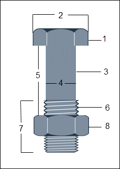
1. Bolt head
2. Bolt head diameter
3. Shank
4. Shank diameter
5. Grip length
6. Thread
7. Thread length
8. Nut
Creating a Pattern of Fasteners
To create a pattern of fasteners, select the fastener from the Model Tree, right-click and select  (Pattern). A pattern of fasteners is created using the selected reference provided the created fastener is a member of a pattern.
(Pattern). A pattern of fasteners is created using the selected reference provided the created fastener is a member of a pattern.Note the following points when defining a pattern of fasteners:
• To create a pattern of fasteners the selected reference must be a part of patterned geometry.
• Issues with references in the pattern can lead to failure to create the pattern of fasteners, or creation of the pattern for only some of the references. The following are some reasons for failure:
◦ Some or all of the selected references do not have matching flanges or holes.
◦ The axis of the reference is not perpendicular to the flanges.
◦ The references are partial cylinders.
◦ Both end flanges are non-planar or non-circular.
If some of the patterned fasteners are created while some fail then you are prompted to create the pattern with only some fasteners, or discard the pattern of fasteners.
• If you try to create a pattern of fasteners on references where fasteners already exist, then the existing fastener is replaced with the fastener that is a part of the pattern. You are prompted to create the new fastener pattern or retain the existing fasteners.
• If geometry is modified such that some pattern instances become invalid, the number of fasteners updates accordingly. If only one instance remains valid, it is still displayed as a pattern node. If all instances become invalid, the pattern node fails in the Model Tree.
• You cannot create a pattern of patterns of fasteners.
• You can only edit a fastener pattern by selecting the pattern node. Multiple fastener selection disables the pattern option.
• Deleting a pattern removes all instances except the original fastener. Deleting all hole instances cause the fastener to fail.
• Patterned fasteners are always named “Pattern of FastenerN” in the Model Tree and in reports, even if only one instance in the pattern is valid.
Guidelines on Fastener Creation
While creating fasteners follow these guidelines:
• Fasteners can only be created on solid bodies.
• Bolt shank diameter must be smaller than the bolt hole diameter.
• Bolt head diameter must be greater than the bolt shank diameter.
• Bolt head diameter must be greater than the bolt hole diameter.
• Fastener materials must be linear isotropic materials only. When defining a fastener with materials that are not included in the standard Fasteners library ensure that you have valid definitions for the following parameters:
Parameter | Unit |
|---|---|
Density | kg/m3 |
Young's modulus | Pa |
Poisson's ratio | N/A |
Thermal expansion coefficient | 1/C |
Tensile yield strength | Pa |
Thermal conductivity | W/m-K |
Specific heat | kJ/kg.C |
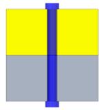
• If all connected flanges have a through-hole then a bolt head is created on both ends of the fastener.
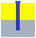
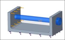
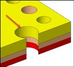
• If one of the flanges does not have a through-hole, the bolt is created with a bolt head on only one end as shown in the following figure (screw type of fastener):
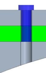
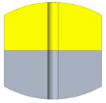
• If all the flanges have through holes, but the lower face of the last flange is not perpendicular to the axis of the hole, then the fastener is created with a bolt head on only one end as shown in the following figure:
If there are only two flanges, and the lower one has a curved end surface, then a fastener cannot be created.
• When creating a fastener, the axis of the fastener must be perpendicular to the flanges.
• The fastener must have connected flanges to function correctly. You must select a minimum of two flanges to create a fastener.
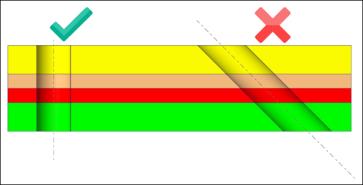
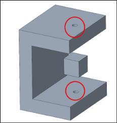
• To create fasteners between flanges that are at a distance from each other but have coaxial holes as shown in the figure below select the check box Create fastener through the separated coaxial holes:
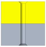
• The end flanges of the selected references must have planar surfaces. If the end flanges have curved surfaces as shown in the following figure, the fastener cannot be created.
• The end flanges of the selected references must have circular edges. Straight edges as shown in the following figure are not allowed and the fastener will not be created.
• The references selected for the fastener definition must be complete cylinders. In the following example the bolt holes are partial cylinders —so the fastener cannot be created.
If there is intervening geometry between the upper and lower flanges, the fastener is created but you get a warning and must consider this point when interpreting the study results.
Fasteners with Varying Dimensions
When creating a fastener passing through multiple references with different dimensions the fastener creation can fail for the following reasons:
• The bolt shank diameter is greater than the bolt hole diameter—This prevents the bolt from fitting into the hole.
• The bolt head diameter is smaller than the bolt shank diameter—This causes the bolt head to pass through the hole, failing to secure the fastener.
• The bolt head diameter is smaller than the bolt hole diameter—The bolt head does not properly secure the fastener.
• No connected flanges were found for the selected reference—To be correctly defined the fastener requires at least two flanges that are in contact.
• No separated coaxial holes were found for the selected references—If you selected the Create fastener through the separated coaxial holes. check box but the selected bolt holes are not coaxial, then the fastener cannot be created.
• The axis of the references is not perpendicular to the flanges.
• No end flanges were found with planar surfaces for the selected references.
• No end flanges were found with circular edges for the selected references