Gage Size Does Not Fall Within the Feature Extent
The specified size dimension is outside of the feature extents. In general, the size dimension should fall within the feature extent. However, it is common practice for Casting, Forging, or Molded parts to show the feature size where material is removed by a fillet or round.
The pictures below show an example of a tapered shaft with two different dimensioning schemes. The scheme shown to the left is a valid method for defining the gage diameter of the feature. The scheme to the right shows the gage diameter of the feature at the reference plane. However, there is a fillet between the feature and the reference plane. The fillet removes the edge where the diameter is specified and therefore falls outside the actual extents of the tapered shaft. Thus, the dimensioning scheme is not recommended because the diameter is difficult to inspect.
|
Valid Gage Size Dimension
|
Invalid Gage Size Dimension
|
|---|---|
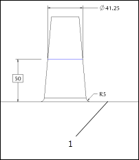 1. Reference plane |
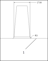 1. Reference plane |
Even if the fillet is not explicitly represented in the CAD model, there may be a small fillet in the physical part in that location, so it is generally poor practice to define the size dimension right at the edge of the feature.
To eliminate this problem, you should probably modify the parametric dimensioning scheme in the CAD model for this feature.