Design Spaces
Design space defines the bodies that take part in the optimization. It includes defining the following:
Starting Geometry
Designating a body as the starting geometry is the first step of defining a generative study. It helps you understand the volume limits. Select a body that represents the volume for the design that you intend to create. The final design is contained inside the starting geometry. Designate only one body as starting geometry. The body designated as the starting geometry becomes partially transparent to provide a better view of the bodies contained inside.
When working within an assembly context, select a body from a part as the starting geometry.
|
|
The following body types are not supported as the starting geometry:
• Body from a sheetmetal part
• Body intersected by an assembly cut
• Body from a flexible component
• Body from a Creo Unite technology
• Body from a part with an existing Generative Design feature
|
Preserved Bodies
If you want certain bodies to be unaffected during optimization, designate them as preserved bodies. These bodies are included in the generated designs, but their geometry remains unchanged. The bodies designated as preserved bodies should not intersect or touch each other; if they do, you should merge those bodies. The preserved bodies should be completely inside the starting geometry volume. The preserved bodies assume the same material as the active material in the active design criteria. You can reference loads and constraints on the surfaces of preserved bodies. The bodies designated as preserved bodies appear in blue. The preserved bodies are listed under the Preserved Geometry node in the Generative Tree.
When working within an assembly context, select the preserved body within the same part of the starting geometry.
Preserved Surfaces
You can also create preserved geometry by offsetting surfaces of the starting geometry. These surfaces are called preserved surfaces. To create them, select the surfaces to be preserved and specify the offset. A rolling ball offset is created around these surfaces inside the starting geometry. The offset is displayed in blue and is listed under the Preserved Geometry node in the Generative Tree.
|
|
When working with a starting shape, you can create preserved surfaces by selecting surfaces of undesignated bodies.
|
Excluded Geometry
The bodies designated as excluded geometries are represented as empty volumes, without any material, in the final generated designs. When designating the bodies to be excluded, you can also create a rolling ball offset around them. This offset creates a clearance between the excluded bodies and the optimized geometry. These bodies act as obstacles as the solution resolves around them, but not within their geometry. The resulting generated designs have a void based on the profile of the excluded geometry. An excluded geometry should be inside or pass through the starting geometry.
When working within an assembly context, select a body as the excluded geometry from the same part of the starting geometry or from a different part in the assembly.
|
|
When an excluded body or the offset of an excluded body intersects or passes through a preserved body, the volume of their interaction is internally subtracted from the preserved body. Avoid this setup as it can cause issues during reconstruction.
|
You cannot apply loads and constraints on a body designated as excluded geometry. Defining excluded geometry is optional. The bodies designated as excluded geometry appear in red.
Undesignated Bodies
The model can have undesignated bodies that can have contact with the starting geometry or other undesignated bodies. These bodies can have loads and constraints applied to their surfaces and can transfer loads and constraints to other bodies with which they have a bonded contact. The undesignated bodies affect the generated design but they are not part of the final design.
It is recommended to create preserved geometry around an undesignated body when the undesignated body is connected to the starting geometry. Specify an offset to create the preserved geometry around the undesignated body inside the starting geometry.
The following image shows the starting geometry, preserved geometry, excluded geometry, and undesignated body:
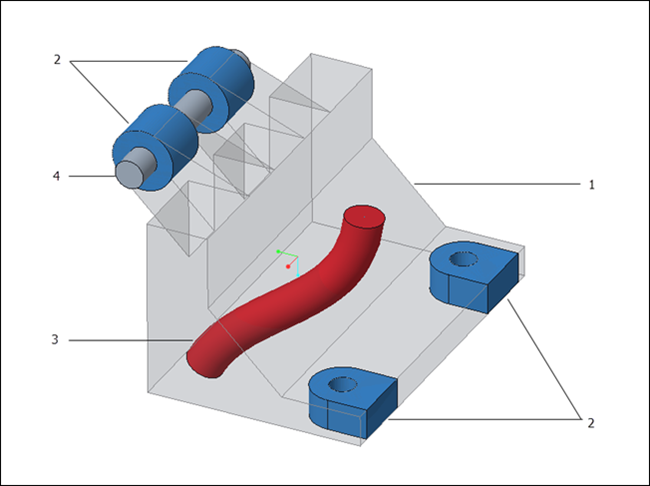
1. Starting geometry
2. Preserved geometry
3. Excluded geometry
4. Undesignated body
If you designate certain bodies as the preserved bodies without defining the starting geometry, Creo Parametric automatically creates the boundaries for optimization as the starting shape. You can still designate a body as the starting geometry. Similarly, if you define the preserved surfaces without defining the starting geometry, a starting shape is created around the preserved surfaces. |
When working within an assembly context, select a body as the undesignated geometry from the same part of the starting geometry or from a different part in the assembly.
To Designate a Body as Starting Geometry
Do one of the following:
• Select a body that you want to optimize from the graphics window or Model Tree and click  Starting Geometry.
Starting Geometry.• On the Generative Design tab, click Starting Geometry and select the body that you want to designate as starting geometry.
Starting Geometry and select the body that you want to designate as starting geometry.The designated body becomes partially transparent.
Only one body can be defined as the starting geometry. |
To add preserved bodies volume to the starting geometry, use the Merge Boolean operation when both the bodies are active. |
To Designate Bodies as Preserved Geometry
Do one of the following:
• Select the bodies in the graphics window or the Model Tree and click  Preserved Bodies.
Preserved Bodies.• On the Generative Design tab, click Preserved Bodies and select the bodies that you want to designate as preserved bodies.
Preserved Bodies and select the bodies that you want to designate as preserved bodies.The preserved bodies appear in blue.
To Designate Surfaces as Preserved Geometry
1. Do one of the following:
◦ Select the solid surfaces in the graphics window and click  Preserved Surfaces.
Preserved Surfaces.◦ On the Generative Design tab, click Preserved Surfaces and select the solid surfaces from the starting geometry.
Preserved Surfaces and select the solid surfaces from the starting geometry.2. [Optional] Specify a name for the preserved surfaces in the Name box.
3. Specify a positive offset value that is greater than three times the element size.
4. Click OK. A rolling ball offset is created around the selected surfaces inside the starting geometry.
The preserved geometry appears in blue.
To Designate a Body as Excluded Geometry
1. On the Generative Design tab, click  Excluded Geometry. The Excluded Geometry dialog box opens.
Excluded Geometry. The Excluded Geometry dialog box opens.2. Select the body as the reference.
3. Optionally, specify the offset.
4. Click OK. A rolling ball offset is created around the selected body.
The excluded bodies appear in red.
To View the Designated Bodies
Expand the nodes under Design Spaces in the Generative Tree to view bodies designated as starting geometry, preserved geometry, and excluded geometry.
You can hide designated bodies from the Model Tree. However, these bodies participate in optimization calculation. |
To Remove the Designation of a Body or Surface
Right-click the body or surface in the Generative Tree and click Remove.
This action does not delete the body or surface. It only removes its designation. |