Converting Harness Parts to Assemblies
Starting with Creo 12, legacy harness parts must be converted to assemblies to leverage new Cabling functionalities. This topic describes the process, tools, and considerations for converting harness parts to assemblies.
|
|
Users can continue working with legacy data but will not benefit from new functionalities unless they convert harness parts to assemblies.
|
To convert a harness part to an assembly, complete the following steps:
1. In the Cabling Tree, select the harness part to convert, right-click it and then select  Convert to Assembly. The Harness Conversion to Assembly dialog box opens.
Convert to Assembly. The Harness Conversion to Assembly dialog box opens.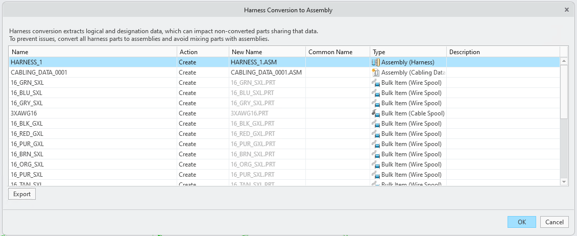
The harness part must be in the master representation and part of an active model. |
◦ The Harness Conversion to Assembly dialog box does the following:
▪ Manages name conflicts and ensures that model names adhere to standard conventions during conversion between feature names and model names.
▪ Embeds the designation and logical data into a newly created Cabling data model.
▪ Converts all existing spools to bulk items and restructures them into the new harness assembly.
▪ Converts cosmetics features into bulk items.
▪ Restructures splices into the new harness assembly.
◦ The Harness Conversion to Assembly dialog box displays the following information in the form of a table:
▪ Name — Lists the original names of the components before conversion
▪ Action — Specifies the action performed on the component:
▪ Reuse — Uses existing library items.
▪ Overwrite — Replaces existing items with new parameters.
▪ Create — Creates new components.
▪ Restructure — Integrates existing splices and custom components into the harness assembly.
▪ Browse — Browse for another component to use.
▪ Rename — Renames family table instances.
When a conflict is detected between the cabling item parameters, right-click the cabling item in the table and select  Show Parameters Conflicts to view mismatched parameters. Only mismatched parameters are shown in the conflict view. Matching parameters are hidden to simplify comparison.
Show Parameters Conflicts to view mismatched parameters. Only mismatched parameters are shown in the conflict view. Matching parameters are hidden to simplify comparison.▪ New Name — Lists the new names assigned to the assembly and bulk items after conversion. The file extensions .PRT and .ASM indicate the file types.
▪ Common Name — A user-friendly name that differs from the actual file name. This special parameter supports more descriptive and flexible naming for parts and assemblies, especially when file names are constrained by character limits. This column is editable and can also be left blank.
▪ Type — Describes the type of converted assembly and bulk items.
▪ Description — Displays errors and warnings of the item.
Click Export to export all errors and warnings to a CSV file. Click OK to complete the harness conversion to assembly or click Cancel to exit the conversion dialog box.
2. The Conversion Review Mode is the final step in the conversion process. It provides a fully functional Cabling environment where users can review and resolve issues introduced during conversion—without committing to the changes. Errors and warnings are displayed in the Notification Center, which serves as the primary troubleshooting tool. As issues are resolved, they are automatically removed from the list. At this stage, users can either finalize the conversion or cancel it to restore the original model state. After reviewing, click  Done to convert the harness part to a harness assembly, or click
  Cancel to revert to the pre-conversion state.
Done to convert the harness part to a harness assembly, or click Cancel to revert to the pre-conversion state.Post Conversion
After completing the harness conversion process, several manual and automated steps are recommended to ensure a clean, functional, and up-to-date design environment. These steps help finalize the transition from legacy cabling data to the new harness assembly structure.
1. Update drawings and manufacturing models
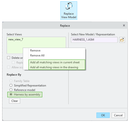
◦ Drawings— Drawing views referencing the original harness part must be manually updated. Use the Replace View Model tool with the new Harness by assembly option to substitute the old part with the new harness assembly.
To streamline updates across multiple views:
▪ Use Add all matching views in current sheet
▪ Use Add all matching views in the drawing
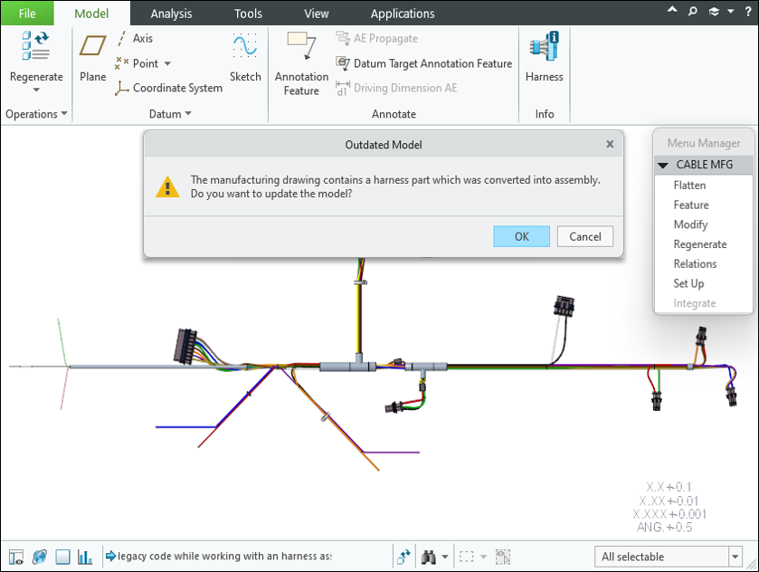
◦ Manufacturing models— Flattened harnesses used in manufacturing are automatically updated upon retrieval.
2. Clean up legacy cabling data— After conversion, legacy cabling data embedded in various components can be safely removed. This cleanup is essential to avoid downstream issues and ensure the harness assembly is fully aligned with the new data model.
Use the Remove Legacy Data tool from the Cabling Data & Components overflow menu to remove outdated cabling data from the harness assembly after conversion.

Legacy spools and terminators remain in the model after conversion. You must delete them manually if they are no longer needed. This operation cannot be undone. To prevent loss of logical or designation data, convert all harnesses in the top-level assembly before proceeding. |
3. Relations Between Original and Converted Harness— During conversion, system-generated relations are created between the original harness part and the new harness assembly. A new harness assembly is created with a unique subtype. The original harness part is retained with a new revision number.
The following system parameters are added to track conversion:
◦ On the new assembly: PTC_CONVERTED_TO_HARNESS = <Original Harness Part Name>, with the additional boolean parameter, CONVERTED_FROM_HARNESS = YES/NO
◦ On the original part, newly created relation links to the new assembly: CONVERTED_TO_HARNESS = CONVERTED_FROM_HARNESS