To Establish a Connection while Creating a Surface
1. Make sure that the > tab is open.
2. To select a connection type, do one of these things:
◦ Move the pointer over a connection symbol, right-click, and choose a connection type from the shortcut menu.
◦ On the Constraints tab, select a connection row, and then under Condition, click the arrow and select a connection type from the list.
These are the connection types:
◦ G0 - Position
◦ G1 - Tangent—Available only when the boundary has a neighbor.
◦ G2 - Curvature—Available only when the boundary has a neighbor.
◦ G3 - Acceleration—Available only when the boundary has a neighbor, and when the surfaces are boundary surfaces or loft surfaces.
◦ Normal—Available only for a planar boundary.
◦ Draft
If you choose G0 - Position or Normal, the connection is created.
3. If you choose Draft:
a. Select a draft reference. The connection is created with a default draft angle of 10 degrees.
b. To change the draft angle, double-click the value, type a new one, and press ENTER. The draft angle is modified.
4. To add or change the reference for a surface connection:
a. Click the Constraints tab.
b. In the Connection table, select the row of the connection to edit.
c. Click the Connection reference collector to activate it, and select a surface or plane reference.
d. If needed, click  to reverse the connection:
to reverse the connection:▪ G0, G1, G2, and G3 connections—Switches between the follower surface and the leader surface, so the leader will be the follower, and the follower will be the leader.
▪ Normal connections—Reverses the normal direction.
Surface connections cannot be edited in Reparameterization mode.
5. For loft surfaces, to define a stretch coefficient value for the connection, do one of these things:
◦ Drag a handle
a. To display the stretch handles, do one of these things:
▪ On the Surface tab, click  Show Stretch Handles.
Show Stretch Handles.▪ On the Constraints tab, select the Show stretch handles check box.
b. Drag the stretch handle.
◦ Define a value
Do one of these things:
▪ Type a stretch value in the graphics window.
▪ Use the Constraints tab:
a. On the Constraints tab, under Connection, select the row of the desired connection.
b. Next to Stretch value, enter a stretch coefficient value.
c. Optionally, to expose the stretch coefficient parameter value so it can be edited outside of the Style environment, click  .
.
.◦ A stretch value of 1 means no stretch to either direction.
◦ A negative stretch value flips the stretch direction.
◦ The stretch value cannot be 0.
Examples
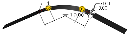
The stretch value is being applied to the connection between the left and the middle surface.
Stretch value 1 (no stretch)
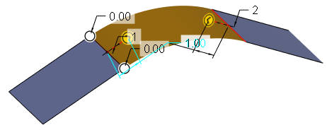
Stretch value 3
The middle surface follows the tangent direction longer.
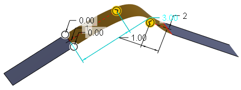
Stretch value -3 (negative)
The middle surface goes in the opposite direction of the tangent, folding under the left surface.

6. Click  OK.
OK.
OK.