Tire Tread—Variable Pull Direction Draft
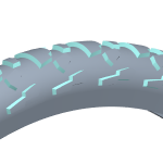
Draft a non-planar surface, like the treads of a tire, using Variable Pull Direction Draft.
In a regular Draft feature, the pull direction is perpendicular to the surface being drafted. It is the direction you would pull the part out of a mold. When the surface is non-planar, the pull direction varies to follow the surface geometry.
Select the pull direction and draft hinges
1. With the  Pull direction collector active, select the top surface of the tread as the pull direction.
Pull direction collector active, select the top surface of the tread as the pull direction.
2. To select the  draft hinges:
draft hinges:a. Click the References tab. Set 1 is selected.
b. Click the Draft Hinges collector.
c. Select the edges along the top surface of the tread in any of these ways:
▪ One at a time
Hold down CTRL while you select edges.
▪ Surface loop
Select the first edge, hold down SHIFT, and hover over the pull direction surface until a preview of the loop appears and the “Surface loop” label shows next to the pointer. Click the surface, and the loop chain is selected.

▪ Range of adjacent edges
Select the first edge, hold down SHIFT, and hover over the last edge until a preview of the chain appears and the “Surface loop from to” label shows next to the pointer. Click the last edge, and a chain of adjacent edges is selected. You could use this if your design intent is to mirror the top edge, then you would not select that edge as a draft hinge.

d. If the geometry is not what you expected, click Flip next to the Draft Hinges collector.
e. To create another set in the same feature, click New set. For each new set, click the Draft Hinges collector, and select curves or edges.
Define the draft angle
1. To define the  draft angle:
draft angle:a. On the References tab, under Sets, select the set.
b. Under Angle, enter an angle value for the set, or drag the angle dragger in the graphics window.

c. For each set, select the set, and enter an angle.
2. Click  OK.
OK.
OK.