EZ Tolerance Analysis Enhancement: Support for Unequally Disposed Profile Tolerances
Creo Parametric 11.0.0.0
User Interface Location:
Videos
Description
EZ Tolerance Analysis now supports unequally disposed profile tolerances for both ASME/ISO GPS models. The following types of geometrical tolerances support these specifications:
• Profile of a surface
• Profile of a line
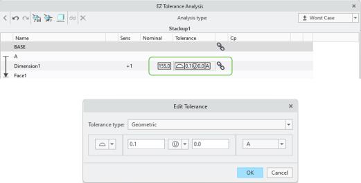
Unequally disposed profiles can be defined for features directly from the EZ Tolerance Analysis Stackup user interface, or they can be validated as linked annotations from an existing geometrical tolerance with semantic references defined. The values that are used by the unequally disposed profile are used in stackup analysis calculations and are displayed in the results.
Unequally disposed profile tolerances are indicated differently in ASME/ISO, and the proper syntax is also different. In ASME, this specification is indicated with the Ⓤ symbol, while in ISO this specification is called Specified tolerance zone offset and is indicated with the letters UZ.
The table below explains how this specification is used in ASME/ISO cases with examples.
In this ASME example, the profile zone has been shifted, so that 0.1 is outside the material and 0.2 is inside the surface. 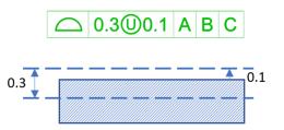 | In this ISO example, the center of the profile zone has been shifted to be 0.15 outside the material of the surface. 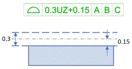 |
Benefits
With this enhancement, models with unequally disposed profiles can now be validated for a 1D stackup analysis, and compliance with the ASME/ISO detailing standards has been improved.
Additional Information
Tips: | None. |
Limitations: | No known limitations. |
Does this replace existing functionality? | No. |
Configuration option associated with this functionality: | None. |