Verification Cases for Thermal Analyses
Heat Transfer in a Composite Wall
Problem Statement: A furnace wall consists of two layers: fire brick and insulating brick. The temperature inside the furnace is 3000 F (Tf) and the inner surface convection coefficient is 3.333 x 10⁻³ BTU/s ft2 F (hf).
The ambient temperature is 80 F (Ta) and the outer surface convection coefficient is 5.556 x 10⁻⁴ BTU/s ft2 F (ha). Find the temperature distribution in the composite wall.
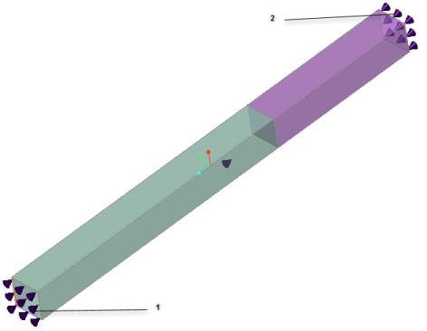
1. Inner Layer:
Film coefficient: 3.333 x 10⁻³ BTU/s (ft2)(F)
Ambient temperature (temperature inside the furnace): 3000 F
2. Outer Layer:
Film coefficient: 5.556 x 10⁻⁴ BTU/s ft2 (F).
Ambient temperature: 80 F
Material Properties | Geometric Properties |
|---|---|
Fire brick: k = 2.222 x 10⁻⁴ BTU/s ft F Insulation: k = 2.778 x 10⁻⁵BTU/s ft F | Cross-section = 1 in x 1 in Fire brick thickness = 9 in Insulating wall thickness = 5 in |
Result Comparison—Simulation quality slider at default position
Results | Target | Creo Simulate | Ansys Discovery Explore | Creo Simulation Live | Percent Error |
|---|---|---|---|---|---|
Minimum Temperature (F) | 336 | 336.64 | 325.70 | 324.23 | 3.50 |
Maximum Temperature (F) | 2957 | 2597.17 | 2959.10 | 2959.30 | 0.08 |
Results Comparison for Creo Ansys Simulation (Default mesh)
Results | Target | Ansys Discovery Refine | Creo Ansys Simulation | Percent Error |
|---|---|---|---|---|
Minimum Temperature (F) | 336 | 336.67 | 336.64 | 0.19 |
Maximum Temperature (F) | 2957 | 2957.20 | 2957.17 | 0.01 |
Conduction in a Composite Solid Block
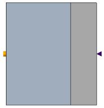
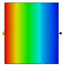
Problem Statement: Consider heat conduction in a wall formed as a composite of two materials. Material 1 has a uniform heat generation source equal to 6000 Watts applied to the outer surface, while Material 2 has an outer surface exposed to convective cooling. Compute the temperature of the adiabatic surface on the left-hand side of the domain.
References: F.P. Incropera, D.P. Dewitt. Fundamentals of Heat and Mass Transfer. 5th Edition, pg.117, 2006.
Material Properties | Geometric Properties | Loading |
|---|---|---|
Material 1: Conductivity = 75 W/m-K Material 2: Conductivity = 150 W/m-K | Dimensions of the block: 70 mm X 80 mm Material 1= 50 mm Material 2 = 20 mm Thickness = 1000 mm | Left surface: Heat flow = 6000 W Right surface: HTC = 1000 W/m2 K and fluid bulk temperature = 30 C All other surfaces are adiabatic. |
Result Comparison—Simulation quality slider at default position
Results | Target | Creo Simulate | Ansys Discovery Explore | Creo Simulation Live | Percent Error |
|---|---|---|---|---|---|
Temperature of the adiabatic surface on extreme left side, in degree C | 165 | 165 | 161.33 | 161.062 | 2.39 |
Results Comparison for Creo Ansys Simulation (Default mesh)
Results | Target | Ansys Discovery Refine | Creo Ansys Simulation | Percent Error |
|---|---|---|---|---|
Temperature of the adiabatic surface on extreme left side, in degree C | 165 | 165.07 | 165.068 | 0.04 |
Heat Transfer from a Cooling Spine
Problem Statement: A steel cooling spine of cross-sectional area A and length L extend from a wall that is maintained at temperature T w . The surface convection coefficient between the spine and the surrounding air is h, the air temperature is T a , and the tip of the spine is insulated. Find the heat conducted by the spine and the temperature of the tip.
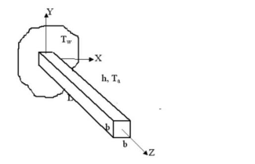
Convection conditions are applied to all 4 longitudinal surfaces.
References: F. Kreith, "Principles of Heat Transfer", 2nd Printing, International Textbook Co.,Scranton, PA, 1959, pg. 143, ex. 4-5
Material Properties | Geometric Properties | Loading |
|---|---|---|
K = 9.71x10⁻³ BTU/s-ft-F | Cross section = 1.2 in x 1.2 in L = 8 in | T w = 100 F T a = 0 F H = 2.778x10⁻⁴ BTU/s-ft2-F |
Result Comparison—Simulation quality slider at default position
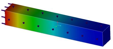
Results | Target | Creo Simulate | Ansys Discovery Explore | Creo Simulation Live | Percent Error |
|---|---|---|---|---|---|
Temperature of Tip, in degree F | 79.0344 | 78.96 | 78.901 | 78.904 | 0.16 |
Results Comparison for Creo Ansys Simulation (Default mesh)
Results | Target | Ansys Discovery Refine | Creo Ansys Simulation | Percent Error |
|---|---|---|---|---|
Temperature of Tip, in degree F | 79.0344 | 79.035 | 79.0343 | 0.00 |