Resultant Measure
What is a resultant measure?
A resultant measure is used to compute the resultant of all forces or moments acting through an imaginary cut in the model, such as the surface of a volume region or a bonded interface between components.
|
|
The imaginary cut is a surface, curve, or edge in a model through which forces or moments act.
|
For example, consider the following model.

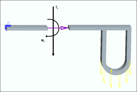
You can use resultant measures to compute the forces and moments acting on one side of the model and transferred to the other side. In other words, the resultant measures allow you to compute the forces and moments acting through an imaginary cut of the model, as shown in the following figure.

To define a resultant measure, select surfaces, surface regions, surfaces of a volume region, edges, or assembly components, across which the force or moment acts. The geometric entities you select must define an imaginary cut through your model, across which you want to compute the resultant force or moment. Use surfaces to define imaginary cuts through volumes, and edges and curves to define cuts through shells.
Note that the imaginary cut must pass completely through the model and must not form an imaginary crack. In the following figure the selected surface passes completely through the model. In this case the resultant measure MR1 is correctly computed.

However in the following figure the resultant measure MR2 will not be correctly computed since the selected surface passes only partially through the model.

Outward Normal Vector
If you select a surface, curve, or edge, a purple arrow that indicates the normal direction of the imaginary cut appears on the model. Click the geometric entity to flip the direction of the arrow and the normal direction of the imaginary cut.
In the previous example, if you want to compute the resultants acting on the section of the model on the right side of the imaginary cut, flip the purple arrow so that it points to the left, as shown below.

To compute the resultants acting on the section of the model on the left side of the imaginary cut, flip the purple arrow so that it points to the right.

Note that the directions of the resultant force and moment depend on the direction of the outward normal of the imaginary cut.
In the assembly mode, you may want to select a surface that is bonded to a surface of another component.
Resultant measures can be either the force or the moment acting through an imaginary cut. |
When you define a resultant measure by selecting components, the coincident surfaces of the two components define the imaginary cut. The order in which the components are selected determines the orientation of the outward normal of the imaginary cut. The outward normal of the imaginary cut points outward from the first component toward the second component. In other words, the resultant measure computes the force or moment acting on the first component, as transmitted by the second component.
For example, if you are working on the following two part assembly.

When defining the resultant measure by selecting components, if you select the blue U-shaped component as the first component, and the gray bar as the second component, the resultant measure is computed as the sum of the two force vector arrows shown in the following figure.

Alternatively, if you select the gray bar component as the first component and the blue U-shaped part as the second component, the resultant measure is computed as the sum of the two force vector arrows shown in the following figure.
