To Create a Point Pattern using a Pattern of Coordinate Systems in Creo Flexible Modeling
Use a pattern of coordinate systems as a reference to place instances of a feature pattern.
1. Create a pattern feature that contains coordinate systems.
2. Select the surfaces to be patterned, and click >  Flexible Pattern. The Pattern tab opens.
Flexible Pattern. The Pattern tab opens.
3. Under Type, select  Point. The Point pattern options appear.
Point. The Point pattern options appear.4. To use coordinate systems in a pattern feature made of datum points to create the pattern, click  From Pattern.
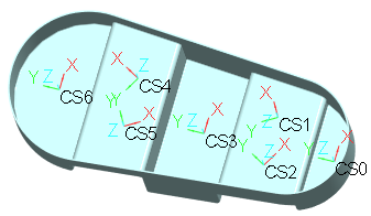
From Pattern.5. To define pattern member placement, make sure the Reference collector is active, and select the pattern header of a pattern feature that is made of coordinate systems.
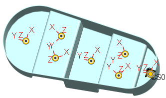
6. The orientation of all the non-lead members of the pattern is according to each respective coordinate system member when a Pattern of Coordinate Systems is selected as a reference.
Optionally, to align the pattern members with the leader by using an origin different from the default origin, click the Use alternate origin collector, and then select a datum point, coordinate system, curve end, or vertex. The default origin is located at the center of an imaginary bounding box around the pattern leader geometry.
The default orientation of the imaginary bounding box is the same as the default coordinate system of the Part. If the orientation of the leader of a reference Pattern of Coordinate Systems is different than the default coordinate system, then you need to align the orientation and origin of the imaginary bounding box with the leader of the Pattern of Coordinate Systems by using the Use alternate origin option, and selecting the first member of the reference Pattern of Coordinate systems.
◦ To attach all pattern members to the model geometry, select the Attach pattern members check box.
When the Attach pattern members check box is not selected, the resulting geometry is a quilt. The appearance of the original solid surfaces is propagated to both sides of the resulting quilt. |
◦ To attach all pattern members to the model geometry with rounds or chamfers of the same type and dimensions as the pattern leader, select the Create rounds/chamfers check box.
8. Click  OK.
OK.
OK.