Working with Drafted Features of Size
Creo EZ Tolerance Analysis supports features of size (hole/shaft or slot/slab) with draft. This means that a drafted hole or shaft has a conical shape, as opposed to a cylindrical shape, and that a drafted slot or slab has sides that are not parallel.
The intent of this functionality is to enable customers who work with injection molded or cast parts containing drafted surfaces to create stackups that directly reference these drafted features of size without having to use workarounds. However, Creo EZ Tolerance Analysis is still only a 1D tolerance stackup analysis tool, and it will not consider any rotational or angular effects when drafted features are used. This section describes some important considerations for using drafted features of size.
Orientation of the Drafted Feature
In the stackup calculations, Creo EZ Tolerance Analysis treats a drafted feature of size as if it were a standard feature of size. As mentioned above, this means that rotational or angular effects are ignored. As a result, the orientation of the drafted feature must still follow the same limitations on its orientation as a standard feature of size.
• The axis of a drafted hole or shaft must be perpendicular to the stackup direction in the same way that the axis of a regular hole or shaft must be perpendicular to the stackup direction.
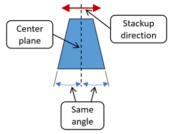
• The center plane of a drafted slot or slab must be perpendicular to the stackup direction in the same way that the center plane of regular slot or slab must be perpendicular to the stackup direction.
◦ The center plane of a drafted slot or slab is a plane at the line of symmetry between the two surfaces of the feature. If the angle between the two sides of the drafted slot or slab is 10 degrees, then the center plane lies midway between the two surfaces at 5 degrees from each of them.
Setting the Nominal Size of the Drafted Feature
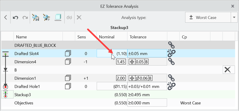
Since drafted features of size are handled in the same way as standard features of size, they must have either a nominal diameter (hole or shaft) or a nominal width (slot or slab). The nominal size is used to calculate any possible assembly shift that may occur between internal and external features that are selected as mating features (assembly constraints). The drafted feature of size is initially set to the minimum size of the feature. That is the smallest distance between the two angled surfaces of a drafted slot or slab, or the minimum diameter of a drafted hole or shaft. You can change the nominal size by clicking on the nominal dimension value in the stackup table.
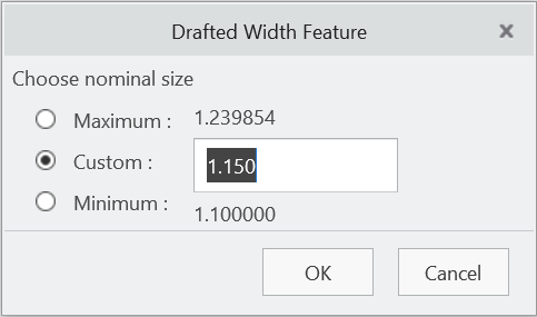
In the Drafted Width Feature dialog box, choose either the calculated maximum or minimum size of the feature, or specify a custom size. The custom nominal size does not need to lie between the maximum or minimum sizes; it can be larger than the maximum size or smaller than the minimum size.
You can modify the tolerance associated with the drafted feature by clicking on the tolerance value.
Acceptable Draft Angles for Drafted Features
Drafted features by default are limited to a draft angle of 5 degrees or less. For drafted holes or shafts, this is the angle of the drafted conical surface measured from the center axis. For drafted slots or slabs, this is the angle of one of the sides of the feature to the center plane.
If you are working with draft angles greater than 5 degrees, it is possible to configure EZtol to accept larger draft angles by changing the DraftAngle setting in the EZTAAppOptions.xml file. See Setting Application Options for additional details.