About Defining a Plate
To add a new plate, right-click a plate and select Add Plate Above or Add plate below. Alternatively, in the Mold Base Definition dialog box, add a new plate by selecting a plate type from the plate list and then clicking a plate. The Plate dialog box opens.
1. Set the unit of measurement as mm or inch. The list of available suppliers is updated.
2. Select a supplier from the list. All available plates appear in the plate list. The selected plate also appears in the preview window.
3. Select the assembly to add the plate from the list on the top right of the dialog box.
4. Plate dimensions appear in the table next to the preview. Double-click the Value column to perform the actions listed below:
◦  Edit the dimension value.
 Edit the dimension value.
◦  Select a valid value from a list.
 Select a valid value from a list.
◦  Select a valid value from a list or enter a value.
 Select a valid value from a list or enter a value.
◦  You cannot change disabled values.
 You cannot change disabled values.
If a Length, Width, or Thickness value entered is not listed in the catalog, the ordering number might change. Manual changes are indicated in the summary tree with a warning  . .Use the Stock Allowance dimension to reduce the thickness of a standard plate. This results in the correct Order Number but allows machining of the ordered plate. |
5. Enter a plate name in the Part Name box. To enter an alternate name, select the check box. Both default names are defined in Part Names on the EMX Options dialog box.
6. Click a tab to preview all available features of the chosen plate type.
7. To set plate property options, select the BOM Data, Parameter, and Relation tabs.
8. Select the Copy Drawings check box on the Options tab to create a drawing from a template.
To save the plate drawings automatically when the plate is assembled to the mold base, set the Configuration Option SAVE_DRAWINGS to YES. |
9. The dimensions of the active feature are displayed in the table. Double-click the Value or Tolerances column to change the dimension value. You cannot change the dimension name.
10. Select the Add to BOM check box to include the component in the Bill of Materials.
11. Click OK to close the dialog box and update the assembly with the new plate, or click Cancel to close the dialog box, and return to the Mold Base Definition dialog box.
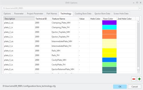
Specify Colors for Plates Using the Technology Tab
You can define the plate colors in Technology tab of the EMX Options dialog box.

• The plate-templates are located at <EMX-loadpoint>/components/%UNIT%/plates. The length, width and thickness of plates can be added as parameter to the models using the following configuration options:
◦ PARAM_PLATE_LENGTH
◦ PARAM_PLATE_WIDTH
◦ PARAM_PLATE_THICKNESS
• If you set the configuration option RECALC_MASS_PROPS to YES, the center of gravity will be calculated for the entire mold base assembly when the Mold Base Definition dialog box is closed.
The position of the point CENTER_OF_GRAVITY in the skeleton model moves to the correct position, so it can be used to drive the position for eyebolts.
By default, the option RECALC_MASS_PROPS is set to NO.
• For each component type, extra layer names can be defined in the Part Names tab. In case a component is assembled, layers or summarize layers are created and the new component is added to the layer. Set the configuration options CREATE_GROUP_LAYER and CREATE_LAYERS_PER_PART if additional layer functionality is required.
• The tolerance mode for all dimensions of the template models is not modified when assembling such a model.
Parent topic