Create a Laminate Section
1. On the graphics toolbar, click Saved Orientations and select TUTORIAL_ORIENTATION_1.
|
|
Scroll down to locate TUTORIAL_ORIENTATION_1.
|
The model orients itself to the orientation TUTORIAL_ORIENTATION_1, as shown in the following graphic:
2. Click  Laminate Section. The Section tab opens.
Laminate Section. The Section tab opens.3. Select the RIGHT datum plane in the Model Tree to specify the Section reference.
4. In the Scale box, type 5, and press Enter. The manual plies in the laminate section are scaled up.
5. Click  OK. A laminate section is created.
OK. A laminate section is created.A laminate section feature LAMINATEXSEC0001 is added to the Composite Tree.
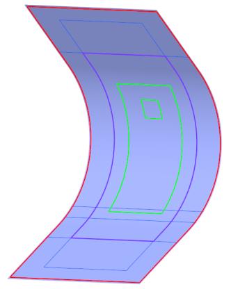
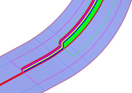
6. Click in the empty space in the graphics window to see the laminate section, as shown in the following graphic:
7. In the Composite Tree, click LAMINATEXSEC0001, and then select  Deactivate on the mini toolbar. The selected cross-section becomes inactive.
Deactivate on the mini toolbar. The selected cross-section becomes inactive.8. Click in the empty space in the graphics window to see the laminate section, as shown in the following graphic:
Change the Order of Plies
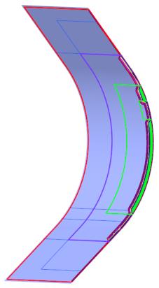
1. On the graphics toolbar, click Saved Orientations and select TUTORIAL_ORIENTATION_2.
The model orients itself, and the laminate section is displayed, as shown in the following graphic:

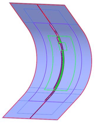
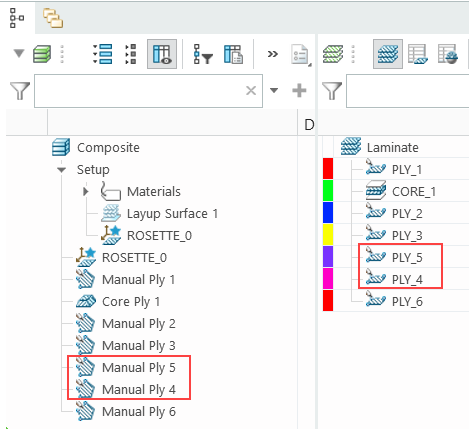
2. In the Composite Tree, drag the Manual Ply 4 feature below the Manual Ply 5 feature. The order of the laminate objects changes in the Laminate Tree.
The laminate section modifies, as shown in the following graphic:
3. On the graphics toolbar, click Saved Orientations and select Default Orientation.