Link PTC Mathcad Input Regions in PTC Creo Parameters Table
1. In PTC Mathcad, click >  Show As List. The Input/Output Designation dialog box opens.
Show As List. The Input/Output Designation dialog box opens.2. On page 2 of the worksheet, press CTRL and select the Piston bore diameter and Effective crankshaft radius definition regions.
3. Ensure  Show in Worksheet is selected.
Show in Worksheet is selected.4. Click >  Assign Input. The Input/Output Designation dialog box opens. The dbore and rcrankshaft parameters are displayed under the Inputs section. The embedded worksheet should look as follows:
Assign Input. The Input/Output Designation dialog box opens. The dbore and rcrankshaft parameters are displayed under the Inputs section. The embedded worksheet should look as follows: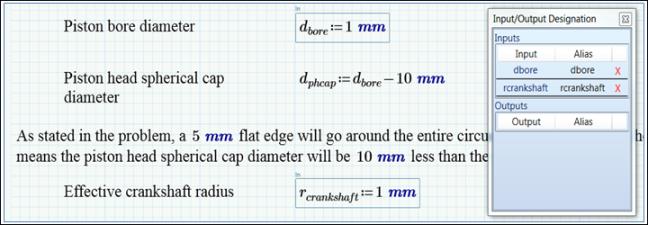
5. From the Quick Access toolbar, click  Save and Push. A confirmation dialog box opens when save and push is completed.
Save and Push. A confirmation dialog box opens when save and push is completed.6. Click OK in the confirmation dialog box.
7. In Creo Parametric, from the Model Tree area, click  Settings >
  Tree Filters.
Settings > Tree Filters.8. Select the Features check box in the Display area and then click OK to exit the dialog box.
9. From the Model Tree area, right-click the first CONNECTING_ROD_ASSEMBLY.ASM, and click Hide.
10. On the Analysis tab, click the arrow below  Measure, and click
  Distance. The Measure: Distance toolbar opens.
Measure, and click Distance. The Measure: Distance toolbar opens.11. From the Graphics toolbar, change the orientation by clicking > .
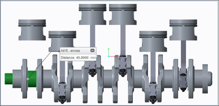
12. Press CTRL and select the two references shown below:
13. From the graphics toolbar, click > .
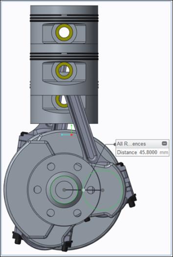
The distance measurement represents the effective radius of the crankshaft (or half of the piston stroke length). |
14. In the Measure: Distance toolbar, click the arrow next to  Save.
Save.
Save.15. Select Make Feature. In the Name column, change the name to CRANK_RADIUS, and select OK.
16. Middle-click to exit the Measure: Distance toolbar.
17. From the graphics toolbar, click > .
18. In the Model Tree area, right-click the first CONNECTING_ROD_ASSEMBLY.ASM and click Show.
19. In the Model Tree area, expand the first PISTON_ASSEMBLY.ASM, and then expand PISTON.PRT, and expand Extrude 1.
20. Click >  Relations.
Relations.21. In the Relations dialog box, under Look In, select Feature.
22. In the Model Tree area, select Section 1.

23. In the Relations dialog box, click > . The dimension names instead of the dimension values appear on the model.
The Creo parameter that represents the piston bore diameter in the Crankshaft assembly is D1:2. |
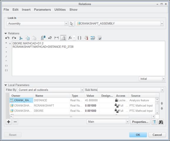
24. In the Relations dialog box, Look In area, select Assembly in the first box and then select CRANKSHAFT_ASSEMBLY in the second box.
25. From the Utilities menu, select the Unit Sensitive check box.
26. Expand Local Parameters at the bottom of the Relations dialog box.
27. Click the arrow next to the Filter By box, and select Current and all sublevels.
28. In the Name column, right-click DBORE, and click Insert to Relations.
29. Type = D1:2 in the Relations area, and press ENTER to move the pointer to the next line.
You can press the EQUAL SIGN to enter =, and select the dimension on the model to enter D1:2. |
30. In the Name column, right-click RCRANKSHAFT, and click Insert to Relations.
31. Press EQUAL SIGN (=).
32. In the Name column, right-click DISTANCE, and click Insert to Relations.
33. Click  to verify the new relations. The Verify Relations confirmation box opens confirming that the relations are successful.
to verify the new relations. The Verify Relations confirmation box opens confirming that the relations are successful.34. Click OK.
35. Click OK to exit the Relations dialog box.
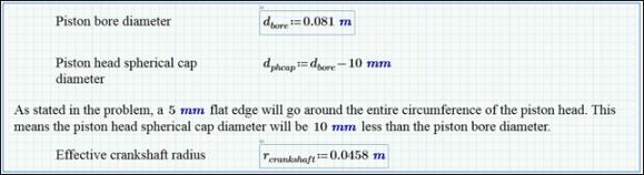
36. In PTC Mathcad, click >  Update Inputs. The worksheet shows the following changes in the Piston bore diameter and Effective crankshaft radius fields.
Update Inputs. The worksheet shows the following changes in the Piston bore diameter and Effective crankshaft radius fields.