Modifying Geometry Using Brushes
The brushes help you manipulate the control mesh. They are especially useful in dense meshes.
To modify geometry using brushes, do the following:
1. Click > > . The Brush dialog box opens.
2. Under Brushes, select a brush.
3. Under Brush Settings, adjust the brush settings to match your needs.
Define Brush Settings
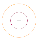
Each brush contains two concentric circles that illustrate brush softness: outer circle and inner circle. The outer circle indicates the brush size.
The softness of the brush is always maximal inside the inner circle and there is a softness gradient between the two circles.
Use the brush settings to define the size, softness, and intensity of brushes.
The following table describes the brush settings:
Brush Setting | Description | Keyboard Shortcuts | ||
|---|---|---|---|---|
Size | Controls the radius of the brush.
This setting is applicable to all the brushes in the Brush dialog box in the current session. | To reduce the brush size, press the Minus key (-). To increase the brush size, press the Plus key (+). | ||
Softness | Controls the softness gradient between the inner circle and the outer circle. This setting is applicable only to the selected brush. | To reduce the brush softness, press Ctrl + Minus (-). To increase the brush softness, press Ctrl + Plus (+). | ||
Intensity | Controls the effect of the brush on the vertices. This setting is applicable only to the selected brush. | To reduce the brush intensity, press Ctrl + Shift + Minus (-). To increase the brush intensity, press Ctrl + Shift + Plus (+). |
Modify Geometry Using Brushes
Use the brushes to modify geometry. Each brush performs a specific task.
The following table describes how to use each brush:
Brush | Function and Usage | ||||
|---|---|---|---|---|---|
 Select | Select mesh elements. • To select the elements, drag the pointer along the geometry. • To add more elements to the selection, press Ctrl and drag the pointer along the geometry. • To remove elements from the selection, press Alt and drag the pointer along the geometry.
| ||||
Erase | Remove or delete control mesh elements. • To remove the elements, drag the pointer along the geometry. • To delete the faces instead of edges, press Shift and drag the pointer along the geometry. | ||||
 Reset | Reset the mesh changes that are made in the active resolution level.
| ||||
 Pull | Pull or push vertices along their average surface normal. • To pull the vertices, drag them away from the surface. • To push the vertices, press Shift and drag the vertices towards the surface.
| ||||
 Move | Move the vertices in screen space orientation. • To move the vertices, drag the pointer along the geometry. | ||||
 Smooth | Smoothen the surface by averaging the location of vertices. • To smoothen the surface, drag the pointer along the surface.
| ||||
 Inflate | Inflate or deflate a beam-like geometry. • To inflate, select the beam-like geometry. Each vertex in the selected area moves away from the surface along its normal. • To deflate, press Shift and select the beam-like geometry. Each vertex in the selected area moves towards the surface along its normal. | ||||
 Flatten | Planarize surfaces by flattening vertices to sampled orientation. To flatten, do the following: 1. Select the geometry or a datum plane to sample an orientation.
2. In the By Angle box, specify the angle that indicates brush influence limit.
3. Drag the pointer along the surface to flatten it. | ||||
 Attach | Connect shape vertices to the selected triangulated mesh. To attach, do the following: • Click Attach and select the triangulation geometry.
|
 Lock
Lock