About Notches and Punches
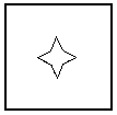
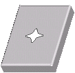
Notch and punch are templates used to cut and relieve sheet metal walls. In Sheetmetal Design, notches and punches both perform the same function and have the same menu commands, so the one you choose depends on your naming convention. Industry standards place notches on edges and punches in the middle of the sheet metal wall.
|
Notch
|
Punch
|
|---|---|
 |
 |
Notches and punches are manufacturing operations made using the following three phases:
• Phase One—Create the desired type of cut on a sheet metal part.
• Phase Two—Convert the cut into a user-defined feature (UDF). This UDF is saved in your directory and can be included in multiple designs. It carries the file name extension, .gph.
• Phase Three—Place the notch or punch UDF on the desired sheet metal part.
You can create a reference part to help place your notch or punch UDF. Typically, you want to keep the reference part simple. The reference part carries the file name extension: gp.prt.
|
|
Create your UDFs in Sheetmetal mode because UDFs created in Part mode do not work on sheet metal parts.
|
|
UDF Reference Part
|
Sheet Metal Punch Placement
|
|---|---|
 |
 |
Each sheet metal notch and punch has a specific tool that defines its shape. The same tool is referred to when and wherever you use that UDF. Because of the tool dimensions, you cannot scale the size of the sheet metal notch and punch UDF. In order to change the size of these UDFs you must reassign the appropriate reference tool used in manufacturing.