Solids Checks
When you click the Solids tab in the Geometry CHECK (VDA standard) dialog box, a tabbed page appears. It contains the following checks:
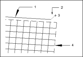
• Distance to Vertex Edge (default check setting: < 0.02 mm)—GeomIntegrityCHECK reports the vertex and the edge in a solid if the distance between the two elements exceeds the tolerance value specified in your configuration file.

a. Edge
b. Vertex to Edge Gap
c. Vertex
d. Face
The point that belongs to a vertex must lie within the configured tolerance on the curve which is a part of the corresponding edge. If the distance between the point and the curve exceeds the tolerance value, the solid is defective.
Recommended solution:
Project the point onto the curve. Otherwise, generate a new one.
In a transfer of solids through neutral interfaces (for example, STEP), a boundary representation (B-rep) is transferred. This is the description of the solid through its bounded surfaces (faces), which represent the direct surface. These faces form the foundation for surfaces and boundary curves. |
Hence, for solids, the quality criteria for a closed (unified) group of faces are also applicable. The criteria for surfaces, bounded surfaces (faces), and topologies are correspondingly applicable to the bounded surfaces of a solid, including its surfaces and boundary curves, that is, the distance from the bounded curves to the surface.
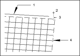
• Distance to Vertex Face (default check setting: < 0.02 mm)—GeomIntegrityCHECK reports the vertex and the face in a solid if the distance between the two elements exceeds the tolerance value specified in your configuration file.

a. Edge
b. Vertex
c. Vertex to Face Gap
d. Face
The point on a vertex must lie within the configured tolerance on the associated bounded surface. If the distance between the point and the face exceeds this value, the solid is defective.
Recommended solution:
Project the point on the face, if possible. Otherwise, generate a new one.
• Deletion of History—GeomIntegrityCHECK reports the B-reps in a solid if they have been imported into the existing model.
• Auxiliary Geometry—GeomIntegrityCHECK reports the solid elements that are hidden from view (for example, cut-off component part areas and dead branches).
In addition, it reports added material in component part areas that are already filled with material, without altering the component part in any way (for example, addition of a ball or sphere to a rectangular solid).
GeomIntegrityCHECK also reports geometrical elements that have no logical relationship to the given solid.
• Cavities—GeomIntegrityCHECK reports solids that are fully contained in another solid and are to be fully subtracted from.
• Multi-Body Solids—GeomIntegrityCHECK reports solids that contain two volumes that do not touch each other. It considers the two volumes to be separate bodies, which is unacceptable in a single solid.
• Multi-Solid Parts—In an assembly environment, there is generally only one solid in one part. If there is more than one solid in a model, GeomIntegrityCHECK reports them as separate solids.
After you have determined all the settings for the Solids checks, click OK to start the checking process, or click Cancel to specify new settings.