Manually Selecting the Parts in the Loop and Selecting Interacting Surfaces
In the New Stackup dialog box, under Assembly, if Select appears in the box, you must manually define the part loop and interfacing features.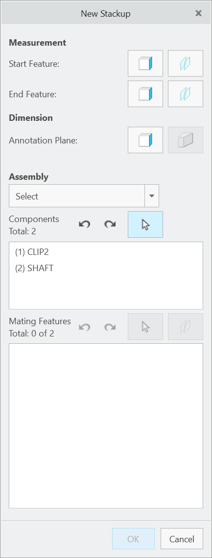 The part associated with the start feature of the Stackup is automatically included in the loop and shown in the Components list. The part appears transparent in the graphics window.
The part associated with the start feature of the Stackup is automatically included in the loop and shown in the Components list. The part appears transparent in the graphics window.1. Select the next part in the loop - the part that mates with the first part. The selected part will also be shown in the Components list and it becomes transparent in the graphics window.
2. Select all parts in the loop ending with the part associated with the end feature in the Stackup definition. All selected parts will be shown in the Components list and the total number of selected components will be shown. After the part loop definition has been completed, all parts are hidden in the graphics window except the first two parts in the Stackup definition. The first part is displayed with normal visibility and the second part is transparent.
• You can undo and redo the component selections individually by picking the Undo or Redo buttons above the Components list. If you want to start over with the component selection, you can pick the Select icon above the Components list. • Select the alignment pins or fasteners that are used to position the parts to one another. The assembly shift through these parts is calculated if the loop definition includes the parts. |
3. After the components are selected, the next step is to select the mating features (assembly constraints) that define how the components interface with each other.
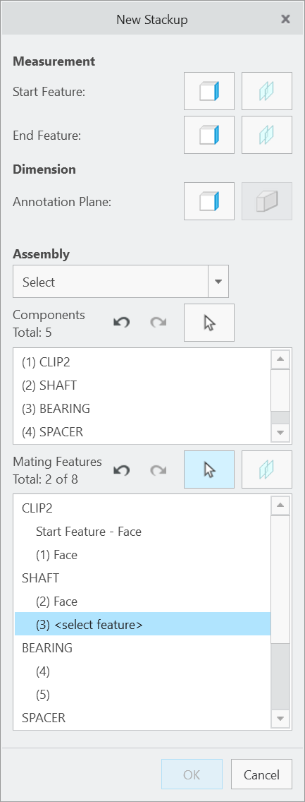
The Mating Features list will be populated with each of the components selected in the previous step. Below each component will be listed a placeholder for each required mating feature.
Select faces, edges, vertices, datum planes, axes, or points to define the assembly constraints between the components. The application will prompt you to select the mating features of each component in sequence as they are listed in the Mating Features list. Select a mating feature from the first part that is referenced in the prompt. The second part is displayed transparent for reference and may not be selected. The total and remaining numbers of mating faces and points appear.
After you select the feature from the first part, the first part becomes transparent and the second part becomes fully visible. You are prompted to select a feature of the second that mates with the first. After this second feature is selected, the first part is hidden and the third part is shown with transparency to help you select the next feature on the second part. This process of showing the part from which you need to define an assembly constraint feature and showing the adjacent part with transparency continues until you select all necessary assembly constraint references. The mating feature currently being prompted will also be shown in the Mating Features list highlighted in blue and with the text <select feature>.
You can undo and redo the mating feature selections individually by picking the Undo or Redo buttons above the Mating Features list. If you want to start over with the mating feature selection, you can pick the Select icon above the Mating Features list. If one of the mating features is a slab or slot, click  to select two parallel surfaces with opposing outward normal to define the slab or slot feature. to select two parallel surfaces with opposing outward normal to define the slab or slot feature. |
4. After all mating features have been selected, the display will change to show all components in the loop as transparent and all mating features will be highlighted to provide a visual confirmation of the Stackup loop.
5. Click OK to complete the Stackup definition.