Wall 5 Axis Finish Sequences: Specific Scenarios
The following are some specific scenarios that you may encounter when using  Wall 5 Axis Finish.
Wall 5 Axis Finish.Scenario 1—Incorrect toolpath orientation after machining outside walls
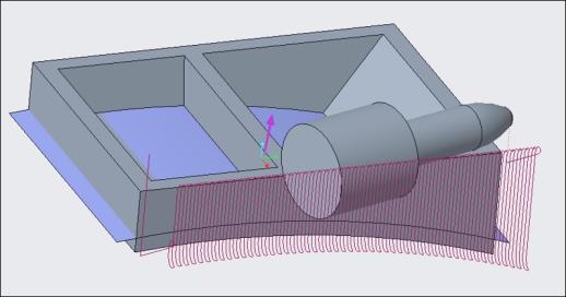
For machining the outside walls, if you select a bottom surface of reference part as floor surface having surface normal pointing downwards, toolpath orientation is incorrect. For example:
To correct the orientation, ensure that the surface normal for wall and floor surfaces must be in same direction. Create a quilt and then correct the direction of the surface normal using  in the floor collector. For example
in the floor collector. For example
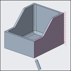
Scenario 2—Incorrect toolpath due to insufficient length of guide curves
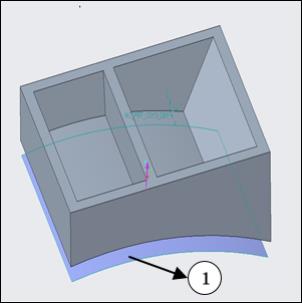
The floor surface is not long enough, not corelated, or lying too far from the wall surface, resulting in incorrect toolpath. For example:
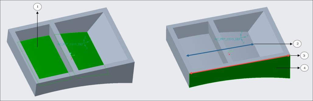
1. Defined floor surface
2. Length of the floor surface
3. Length of the wall surface
4. Defined wall surface
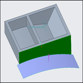
To correct the toolpath, ensure the following:
• The floor surface is long enough to cover the entire length of the wall surface for correctly extracting the guide curves.
• The floor surface must lie on the machining side of the wall surface for correct detection of the guide curves.
For example:
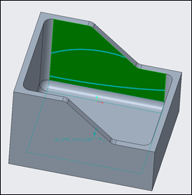
Scenario 3—Incorrect toolpath due to curves selection
For the Morph between two curves pattern type option, when the selected two curves are longer than the machining surface, it results in incorrect toolpath. For example:

To correct the toolpath, the user-defined guide curves must start and end on the machining wall surface boundary. These curves must not extend beyond the surface boundary. For example:
Scenario 4—Incorrect toolpath due to floor surface intersecting and lying between top and bottom of the wall surface
If the floor surface intersects and lies between top and bottom of the wall surface, an incorrect toolpath is generated. For example:
To generate the correct toolpath, floor surface can be at the bottom edge of the wall surface or below the wall surface by tool radius, but not intersecting the wall surface. For example:
1. Floor surface offset by tool radius
Scenario 5—Toolpath is not generated and an error message is displayed
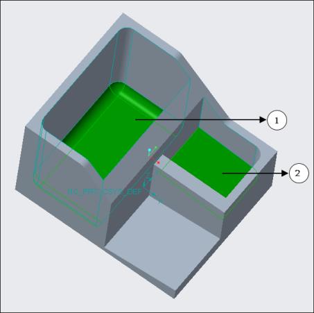
No toolpath is generated if the wall surfaces are joined together and one wall surface does not have a corresponding floor surface. For example:
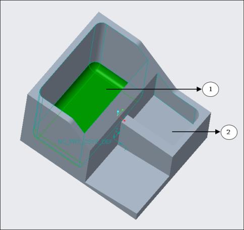
1. First pocket with defined floor surfaces
2. Second pocket without defined floor surface
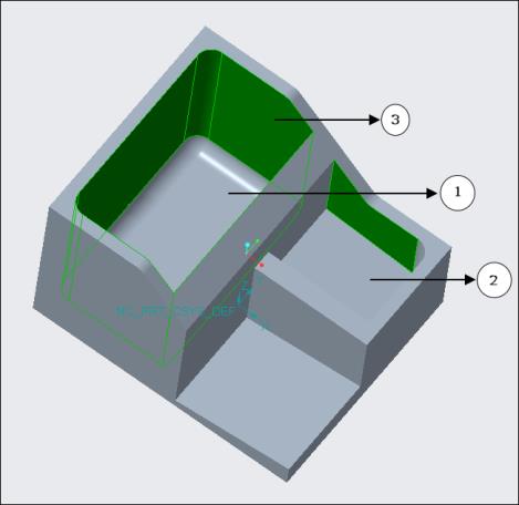
1. First pocket
2. Second pocket
3. Defined wall surfaces
To generate the toolpath on selected wall surfaces of both the pockets, select the floor surface corresponding to the wall surface of the second pocket. For example:
1. First pocket with defined floor surfaces.
2. Second pocket with defined floor surface.
To generate the toolpath only on the wall surfaces of the first pocket, use mill surfaces in the wall surface collector, copy all required surfaces, and then exclude the extra contour. This ensures that the wall surface, which does not have a corresponding floor surface, is removed. For example:

1. Extra surface contour excluded