Tool Parameters
Each type of tool has a set of parameters which describe the geometry of the tool. The parameters for each type of tool are listed in a tool parameters table for each tool type and are explained in the illustrations that follow. The bold cross (:) shown in these pictures for each type of tool indicates the default tool control point, that is, the point for which the tool path will be calculated.
Turning Tools
|
Turn
|
Turn Groove
|
|
|---|---|---|
|
NOSE_RADIUS
|
·
|
·
|
|
TOOL_WIDTH
|
·
|
·
|
|
SIDE_WIDTH
|
·
|
|
|
LENGTH
|
·
|
·
|
|
SIDE_ANGLE
|
·
|
·
|
|
END_ANGLE
|
·
|
·
|
|
GAUGE_X_LENGTH
|
·
|
·
|
|
GAUGE_Z_LENGTH
|
·
|
·
|
|
TOOL_MATERIAL
|
·
|
·
|
|
HOLDER_TYPE
|
·
|
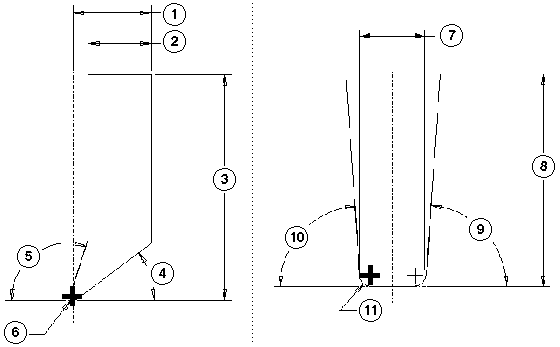
Turn
1—SIDE WIDTH
2—TOOL WIDTH
3—LENGTH
4—END ANGLE
5—SIDE ANGLE
6—NOSE RADIUS
Turn Groove
7—TOOL WIDTH
8—LENGTH
9—SIDE ANGLE
10—END ANGLE
11—NOSE RADIUS
Milling Tools
Mill | Side Mill | Thread Mill | Groove | |
|---|---|---|---|---|
CUTTER_DIAM | · | · | · | · |
CORNER_RADIUS | · | · | · | |
CUTTER_WIDTH | · | |||
SHANK_DIAM | · | |||
LENGTH | · | · | · | · |
INSERT_LENGTH | · | |||
END_OFFSET | · | |||
SIDE_ANGLE | · | · | ||
GAUGE_X_LENGTH | · | · | ||
GAUGE_Z_LENGTH | · | · | · | |
NUM_OF_TEETH | · | · | · | |
TOOL_MATERIAL | · | · |
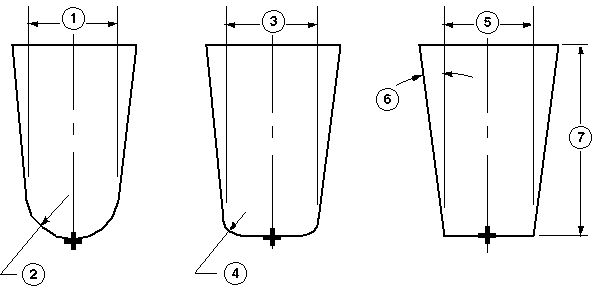
For a ball endmill, you can set CUTTER_DIAM to \u201c-\u201d. Creo NC drives the tool by its corner radius.
Ball Endmill
1—CUTTER DIAM d
2—CORNER RADIUS r=d/2
Radius Endmill
3—CUTTER DIAM d
4—CORNER RADIUS 0 < r < d/2
Flat Endmill
5—CUTTER DIAM d
6—SIDE ANGLE
7—LENGTH
Side Milling Tools
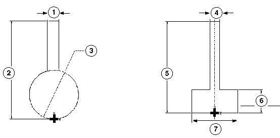
1—SHANK DIAM
2—LENGTH
3—CUTTER DIAM
4—SHANK DIAM
5—LENGTH
6—CUTTER
7—CUTTER DIAM CORNER_RADIUS - (or 0)
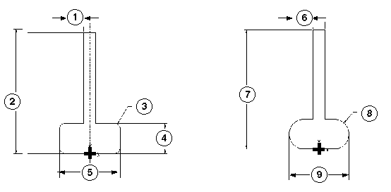
1—SHANK DIAM
2—LENGTH
3—CORNER RADIUS
4—CUTTER WIDTH
5—CUTTER DIAM
6—SHANK_DIAM
7—LENGTH
8—CORNER RADIUS
9—CUTTER DIAM
Thread Milling Tool
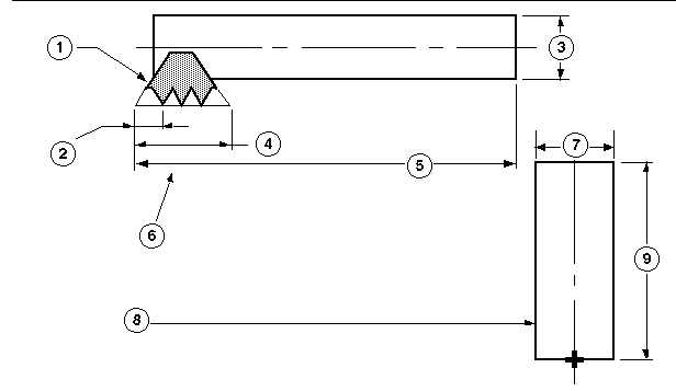
1—insert
2—END OFFSET
3—CUTTER DIAM
4—INSERT LENGTH
5—LENGTH
6—Thread Mill tool parameters.
7—CUTTER DIAM
8—Tool parameters INSERT_LENGTH and END_OFFSET are not reflected in the tool section display. The tool is shown like this.
9—LENGTH
Groove, Contouring, and Auxiliary Tools
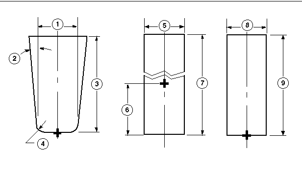
Groove
1—CUTTER DIAM
2—SIDE ANGLE
3—LENGTH
4—CORNER RADIUS 0 <= r <= d/2
Contouring (Wire EDM)
5—CUTTER DIAM (Unlike other tools, you can set the CUTTER_DIAM of a Contouring tool to be 0)
6—1/2 LENGTH
7—LENGTH
Auxiliary
8—CUTTER DIAM
9—LENGTH
Auxiliary | Contouring | |
|---|---|---|
CUTTER_DIAM | · | · |
LENGTH | · | · |
Holemaking Tools
Drill | Csink | Tap | Ream | Center Drill | Bore | Back Spot | |
|---|---|---|---|---|---|---|---|
CUTTER_DIAM | · | · | · | · | · | · | · |
POINT_DIAMETER | · | · | · | ||||
DRILL_DIAMETER | |||||||
BODY_DIAMETER | · | ||||||
LENGTH | · | · | · | · | · | · | · |
CHAMFER_LENGTH | · | ||||||
DRILL_LENGTH | · | ||||||
INSERT_LENGTH | · | ||||||
TIP_OFFSET | · | ||||||
GAUGE_OFFSET | · | ||||||
CUTTING_OFFSET | · | ||||||
SIDE_ANGLE | · | ||||||
POINT_ANGLE | · | · | · | ||||
CSINK_ANGLE | · | · | |||||
GAUGE_X_LENGTH | · | · | · | · | · | · | · |
GAUGE_Z_LENGTH | · | · | · | · | · | · | · |
TOOL_MATERIAL | · | · | · | · | · | · | · |
Drill and Tap
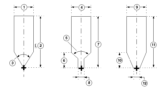
Drill—Regular
1—CUTTER DIAM
2—LENGTH
3—POINT ANGLE
Drill—Elongated
4—CUTTER DIAM
5—POINT ANGLE
6—TIP OFFSET
7—LENGTH
8—POINT DIAMETER
Tap
9—CUTTER DIAM
10—CHAMFER OFFSET
11—LENGTH
12—POINT DIAMETER (can be 0)
Countersink
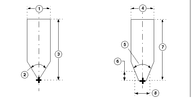
Countersink—Regular
1—CUTTER DIAM
2—POINT ANGLE
3—LENGTH
Countersink—Truncated
4—CUTTER DIAM
5—POINT ANGLE
6—GAUGE OFFSET
7—LENGTH
8—POINT DIAMETER
Bore and Back Spotting
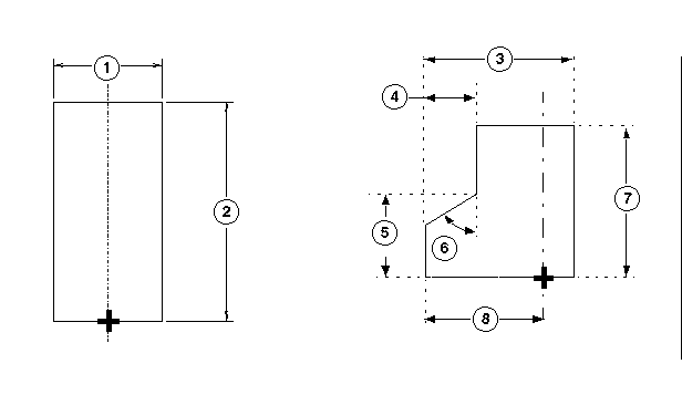
Bore
1—CUTTER DIAM
2—LENGTH
Back Spotting
3—BODY DIAMETER
4—CUTTING OFFSET
5—INSERT LENGTH
6—CSINK ANGLE
7—LENGTH
8—CUTTER DIAM / 2
Ream and Center Drill
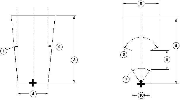
Ream
1—SIDE ANGLE
2—SIDE ANGLE
3—LENGTH
4—CUTTER DIAM
Center Drill
5—CUTTER DIAM
6—CSINK ANGLE
7—POINT ANGLE
8—LENGTH
9—DRILL LENGTH
10—DRILL DIAMETER
Barrel Tools
Barrel Lens | Barrel Tangent | Barrel Taper | |
|---|---|---|---|
CUTTER_DIAM |  |  |  |
CORNER_RADIUS |  |  |  |
LENGTH |  |  |  |
CONVEX_TIP_RADIUS |  | ||
PROFILE_RADIUS |  |  | |
POINT_DIAMETER |  | ||
UPPER_RADIUS |  | ||
SIDE_ANGLE |  |
Barrel Lens
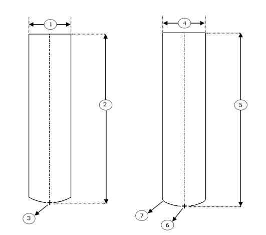
1—CUTTER DIAM
2—LENGTH
3—CONVEX TIP RADIUS
4—CUTTER DIAM
5—LENGTH
6—CONVEX TIP RADIUS
7—CORNER RADIUS
Barrel Tangent
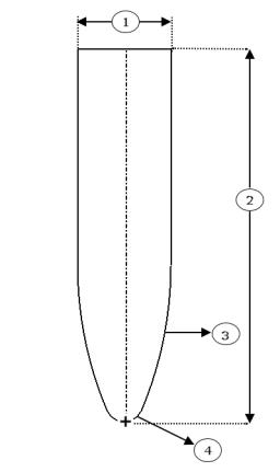
1—CUTTER DIAM
2—LENGTH
3—PROFILE RADIUS
4—CORNER RADIUS
Barrel Taper
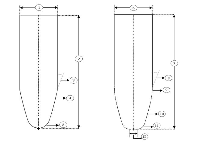
1—CUTTER DIAM
2—LENGTH
3—SIDE ANGLE
4—PROFILE RADIUS
5—CORNER RADIUS
6—CUTTER DIAM
7—LENGTH
8—SIDE ANGLE
9—UPPER RADIUS
10—PROFILE RADIUS
11—CORNER RADIUS
12—POINT DIAMETER