About CMM
CMM is an optional module of Creo Parametric, which provides the tool to generate inspection programs for Coordinate Measuring Machines (CMMs). CMMs will use these programs to probe manufactured parts and provide tolerance deviation analyses for dimensions and geometric tolerances. CMM supports probing using fixed, as well as manually and automatically indexed, probes. Using CMM, you can create fully associative, and parametrically defined, measuring sequences relative to Creo Parametric models. You can also define steps that instruct the CMM to construct geometric entities and reference coordinate systems relative to measured data, and then to perform dimensional and geometric tolerance analyses on the entities, with respect to reference coordinate systems. CMM provides dynamic display of the probe assembly along the path of the probe tip, and allows changing the probe, the active tip, and tip orientation at different points along the path to enable interference checking.
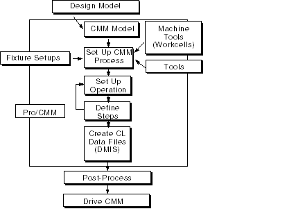
The illustration below summarizes the CMM process.

A Typical CMM Session
The CMM process may consist of the following steps:
1. Create or retrieve a CMM model. To create a new model, bring a reference model (previously created in Part mode) into the CMM session. You can assemble or create additional parts, if desired.
To avoid creating a circular reference, set up the CMM model (that is, retrieve the reference part) before you start the CMM process setup. |
2. Set up the CMM process:
◦ Define the workcells (machine tools) that you will be using to create the Measurement Sequences. Specify the workcell parameters and probes available. This step is not required at this time; it can be performed later, when setting up an operation.
◦ Select or create the probes to be used in the CMM process. CMM probes are defined as Creo Parametric parts or assemblies with a certain set of parameters. If you have LIBRARY access, you can also use standard probing tools from the TOOLING library. This step is also optional at this time; you can select or create probes later, when specifying or modifying a workcell for the operation. However, you have to set up the probe before you start defining a Measure step which uses this probe.
The terms "probe" and "tool" are used interchangeably throughout this documentation. |
◦ Define the fixture setup(s), if desired. Fixtures are Creo Parametric parts or assemblies. You may create your own fixtures, or use standard library fixtures (with LIBRARY access, you can use standard fixtures from the TOOLING library). The fixtures will be displayed along with the CMM model, and are useful for creating probe paths that do not interfere with the holding fixture.
◦ Set up the CMM sites, i.e., files of measure parameters, to be used in creating Measure steps. This step is optional.
◦ Set up an operation:
▪ Supply an operation name. Additional data can be supplied as operation comments.
▪ Specify a workcell that you will be using to create the Measurement Sequences. If the workcells have been previously defined, you can just select the one you need; otherwise, define the workcell at this point and add the necessary probes.
▪ Select or create the coordinate system to be used as the origin (0,0,0) for the probe coordinates output.
▪ Define the FROM and HOME points.
3. Define sequences of steps for the operation.
◦ To create a Measure Step:
▪ Select a type of Measure Step: Plane, Cylinder, etc.
▪ Select a probe to be used. Change tip, if desired (when you first set up a probe, Tip1 will be used as default). For rotating probes, you can also change orientation.
▪ Specify a different reference coordinate system, if desired.
▪ Specify a name, if desired. If not, a default name will be given by the system.
▪ Set up the measure parameters.
▪ Specify the geometric reference(s) for the Measure step.
▪ Specify the measure points, either by manually picking on the screen, or by supplying the number of points in each direction and letting the system automatically generate the points. Manually add, delete, or move the measure points, if desired.
▪ Change the probe path, if desired, by inserting additional moves, specifying entry and exit path, etc.
▪ Supply a comment, if desired.
▪ Set up the SAVE tag for DMIS output, if desired.
◦ To create a Construct Step:
▪ Select a type of Construct Step: Plane, Cylinder, etc.
▪ Specify a name, if desired, If not, a default name will be given by the system.
▪ Specify the type of Construct entity, if multiple types can be generated (e.g., for Plane: Best Fit, Midplane, Normal, Parallel).
▪ Select Measured or Constructed entities as references for the new Construct entity.
▪ Supply a comment, if desired.
▪ Set up the SAVE tag for DMIS output, if desired.
◦ To create a Verify Step:
▪ Specify a name, if desired, If not, a default name will be given by the system.
▪ Select dimension or geometric tolerance (gtol) to verify.
▪ Select feature(s) that this dimension or gtol controls.
▪ Select datum(s) that this dimension or gtol is based on, if required by the type of verification.
▪ Specify a different reference coordinate system, if desired.
▪ Supply a comment, if desired.
4. If necessary, you can modify Measure steps by changing probe, parameters, etc. You can also redefine the way a step is created, or which operation it belongs to.
5. Output the probe path to a file and post-process it to use in a Coordinate Measuring Machine.
6. Create a route sheet at the end of the process.