About Defining the Mold Base Assembly
A mold base is the set of plates and major components that hold the core/cavity insert.
1. Click > . The Mold Base Definition dialog box opens.
2. Define the following variables in the Mold Base Definition dialog box:
◦ Select a supplier from the list of available mold base suppliers.
◦ Select the size from the list of mold base sizes. Existing size-dependent component dimensions are automatically updated when the size is changed.
The unit of measurement is the same as defined in the project. |
3. Select or clear the Show Cavity check box to show or hide the cavity insert assembly outline in the top and side view.
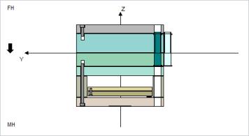
The outline of the cavity insert assembly, represented by a blue box, is calculated while classifying the insert assembly and is displayed in the preview window. The representation enables the user to set up the cavity layout and select the best fitting mold base size. |
4. Click an icon at the top of the dialog box to access other dialog boxes in which you can define the component:
◦  —Opens the Load EMX Assembly dialog box.
 —Opens the Load EMX Assembly dialog box.
◦  —Opens the Save EMX Assembly dialog box.
 —Opens the Save EMX Assembly dialog box.
◦  —Clears all the components in the mold base
 —Clears all the components in the mold base
A dynamic view of the current mold base definition appears in the preview window.

Use the mouse wheel to zoom and click and hold the middle-mouse button to pan in the view.
From the preview window you can view or position new components, and identify components to modify or delete.
5. Right-click a component in the preview window to add guides and plates or to modify and delete the component.
Double-click a component to open the Component dialog box.
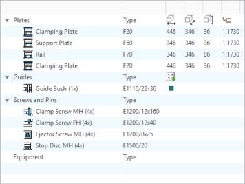
A summary tree appears under the dynamic view. This summary tree contains all defined components inside of the mold base definition.

The tree is divided into four nodes:
◦ Plates—All plates, including the type, the major dimensions and the material value
◦ Guides—All guides, including the ordering number and the number of assembled instances. Additionally, the color of the selected guide pattern appears
◦ Screws and Pins—All screws and pins, including the ordering number and the number of assembled instances
◦ Equipment—All other equipment components, including the ordering number and the number of assembled instances
6. Right-click a node to add guides or plates or to modify and delete the component. Double-click a component to open the Component dialog box.
7. Click  to reset the zoom for side and top views.
 to reset the zoom for side and top views.
8. Click  and select a component to delete. The component is highlighted in red. Click Yes at the prompt to delete it.
 and select a component to delete. The component is highlighted in red. Click Yes at the prompt to delete it.
9. Select  MH (moving half) or
  FH (fixed half) to toggle the view for the bottom preview window.
 MH (moving half) or
  FH (fixed half) to toggle the view for the bottom preview window.
10. To add a new plate, right-click an existing plate and select either Add plate above or Add Plate Below. The new plate is placed either above or underneath between the selected plate. You can also select the new plate and right-click outside the stack to place the new plate on top of the Moving Half or Fixed Half stack. The Plate dialog box opens.
11. Alternatively, add a new plate, by selecting a plate type from the list under the summary tree, and then select an existing plate. The new plate is placed between the selected plate and the splitting plane. You can also select the new plate and click outside the stack to place the new plate on top of the Moving Half or Fixed Half stack. The Plate dialog box opens.
12. To add guide components right-click a plate and click Add guide.
13. Add any of the following types of components to the assembly:
◦  Locating Ring MH
 Locating Ring MH
◦  Locating Ring FH
 Locating Ring FH
◦  Thermal Insulation Plate MH
 Thermal Insulation Plate MH
◦  Thermal Insulation Plate FH
 Thermal Insulation Plate FH
◦  Sprue Bushing
 Sprue Bushing
◦  Support Bushing
 Support Bushing
◦  Knockout
 Knockout
◦  Side Interlock
 Side Interlock
◦  Top Interlock
 Top Interlock
a. When you select a component, a dialog box opens for the selected component in which you can define the component. Equipment components are automatically placed in the correct location. Before you add a guide component, select the active main guide pattern on the left side of the dialog box.
You can define up to three different patterns for the main guides. |
b. Choose a guide component:
▪  Centering Sleeve
 Centering Sleeve
▪  Centered Guide Bush
 Centered Guide Bush
▪  Guide Bush
 Guide Bush
▪  Centered Leader Pin
 Centered Leader Pin
▪  Leader Pin
 Leader Pin
▪  Ejector Guide Bush
 Ejector Guide Bush
▪  Ejector Leader Pin
 Ejector Leader Pin
▪  Puller Pin
 Puller Pin
▪  Puller Bolt
 Puller Bolt
c. Choose additional components such as screws, stop system components, and so on to add from the default component list under the top preview window:
▪  Clamp Screw MH
 Clamp Screw MH
▪  Clamp Screw FH
 Clamp Screw FH
▪  Ejector Screw MH
 Ejector Screw MH
▪  Ejector Screw FH
 Ejector Screw FH
▪  Rail Screw
 Rail Screw
▪  Rail Dowel Pin
 Rail Dowel Pin
▪  Return Pin/Back Pin
 Return Pin/Back Pin
▪  Stop Disc MH
 Stop Disc MH
▪  Stop Disc FH
 Stop Disc FH
▪  Stop Pin MH
 Stop Pin MH
▪  Stop Pin MH
 Stop Pin MH
▪  Tubular Dowel
 Tubular Dowel
▪  Compression Spring
 Compression Spring
d. Define the new components in the dialog box. The components are automatically placed.
14. Select  Front or
  Top to toggle view type. The view changes from side to top view. In the top view all major patterns are displayed as circles and rectangles.
 Front or
  Top to toggle view type. The view changes from side to top view. In the top view all major patterns are displayed as circles and rectangles.
15. The summary tree is updated and the list of patterns inside the mold base appears. The major nodes are listed below:
◦ Guide Patterns—A list of all guides related patterns, including the number of active pattern members, the visibility status, the width and length, and the number in the width and length direction.
◦ Other Patterns—A list of all other patterns, including the number of active pattern members, the visibility status, the width and length, and the number in the width and length direction.
16. To change pattern settings, either double-click a pattern inside the view or the summary tree or right-click a pattern. The Pattern dialog box opens.
17. Select a guide pattern from the summary tree under the bottom preview window. There are four main guide patterns  and two ejector guide patterns (
 or
or  ) in the list. A dialog box for the selected guide in which you can set pattern data, opens.
 and two ejector guide patterns (
 or
or  ) in the list. A dialog box for the selected guide in which you can set pattern data, opens.
18. Select a screw or stop system pattern from the list under the bottom preview window. A dialog box for the selected item opens. Define the pattern before placing a new component:
◦  Clamp Screw MH
 Clamp Screw MH
◦  Clamp Screw FH
 Clamp Screw FH
◦  Ejector Screw MH
 Ejector Screw MH
◦  Ejector Screw FH
 Ejector Screw FH
◦  Rail Dowel Pin
 Rail Dowel Pin
◦  Rail Screw
 Rail Screw
◦  Return Pin/Back Pin
 Return Pin/Back Pin
◦  Stop System MH
 Stop System MH
◦  Stop System FH
 Stop System FH
◦  Side Interlock
 Side Interlock
◦  Top Interlock
 Top Interlock
19. Click the list box next to the zoom tool to select the active main guide pattern. A new guide component is added to the active pattern that appears in the bottom preview window. Set the correct pattern before adding a new guide component.
20. Click Close to close the dialog box.