About Screws
Use screws to join components and use shoulder screws that are similar to latch locks to control plate movement. Click > to define a new screw.
You can place screws with a counterbore in the first component, and a straight hole or blind hole in the last component. When you select One Plate the screw is assembled on only one plate.
The placement references for screws always contain a surface and a thread surface.
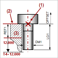
The following image shows the placement references in a screw:

1. Point or axis
2. Surface
3. Thread Surface
The distance between the two surfaces (2) and (3) is measured and displayed in the REF1 reference distance.
The dimension 12.0, displayed in red, indicates that the fixed length of the screw in the tapped hole is more than the default thread depth. You must modify the length LG1 or the thread depth in the cutout dimension T4 and T5.

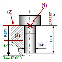
1. Point or axis
2. Surface
3. Thread Surface
In case a shorter screw instance is selected, the threaded depth dimension is displayed in green, indicating that the selected length is appropriate.