Table Customisation Panel
This topic describes the Table Customization panel and its key sections.
Table Type
The Table Type section determines which table will be customized during the flattening process. All tables previously generated by HMX, for example, Wire List, Bill of Materials, and the Cavity Table, can be modified to your specification. If a table customization file already exists for this table in the working directory, then a visual representation of the table appears in the table preview window.
Visibility
The  button toggles a table’s visibility on or off. Turning the table visibility off prevents the table from being created. See the below example, where the wire list table and BoM table are visible, but the cavity table visibility is turned off.
button toggles a table’s visibility on or off. Turning the table visibility off prevents the table from being created. See the below example, where the wire list table and BoM table are visible, but the cavity table visibility is turned off.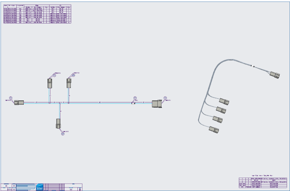
Column Properties
When customizing a table, you can determine which parameter type to add to a new column. You can select from seven primary categories: Wire/Cable, Conductor, Spool, Connector, Pin/Entry Port, Model or BOM. After the category is set, select from a list of parameters. The column parameters are retrieved from the current model.

The Column Header Name text field is used to provide a custom name for each column parameter selected. A column cannot be created without a column name.
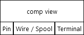
The table preview window provides a preview of the configured layout of the table, including columns, column headers, and any additional information that will be displayed in the table. To scroll the table preview window, hold the left mouse button on the window and drag the mouse left or right. The next figure shows an example of the table preview window with the default cavity table layout.
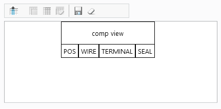
The Column toolbar enables you to configure columns in a table.

Icon | Description |
|---|---|
 Create Column Create Column | To create a new column, select a parameter type, a parameter, and the enter the column a header name. Click Create Column. The new column will be visible in the table preview window. |
 Merge Column Merge Column | To merge two columns, select a column in the table preview window, click Merge Column, and then select the second column to be merged. This process can be repeated to merge multiple columns into one. |
 Unmerge Unmerge | To unmerge columns, select a merged column in the table preview window, and then click Unmerge. All merged columns will restore back to individual columns. |
To delete a column, select a column in the table preview window, and then click Delete Column. | |
 Save Table. Save Table. | Saves the configured tables to the table customization file. |
Resets the table preview to the default. |
Column Constraints
Consider the following constraints when creating a new column:
• The maximum number of columns allowed per table is 50.
• The maximum width for an individual column is 81 characters.
• A minimum of two columns are required to draw cavity views in a cavity table.
• Only parameters that exist within the Creo model can be represented in the table.
• Parameters must be derived from the model or electrical parameters.
• Columns with a FROM or TO grouping can only be merged with other columns with the same grouping.
• Ungrouped columns can only be merged with other ungrouped columns.
General Table Creation Options
Options that can affect all tables are available in the General Table Creation Options.
Merged Column Separator
The separator used in the column headers of merged columns can be customized. The default separator is a forward slash “/”, shown in an example table preview below.
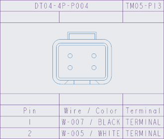
The example output in the flattened drawing appears next.
Include shields in tables
The option Include shields in tables controls the inclusion of shield conductors in the Wire List and Cavity Tables.
If the option Include shields in tables is selected, any shields that are fully routed and are complete will appear in the generated tables. An advanced license is required for this functionality.
If this option is not selected (default), no shield conductors will be included in the tables.