Table Configuration Panel
The Table Configuration panel provides additional customization options for each table type.
The Table Configuration panel and its key sections are displayed below.

Wirelist Table Customizations
Sort Order
The Wirelist has two sorting options:
• Default—Lists the wires and cables in the Wirelist in the order they appear in the Model Tree.
• Alphanumeric—Lists the wires and cables in the Wirelist in order of Wire/Cable parameter Name. The Wire/Cable parameter Name does not need to be included in the Wirelist table for this sorting to be applied.
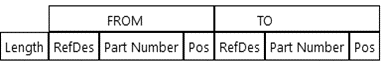
Group From and To columns together
When the Group From and To columns together option is selected, the directional columns are grouped together under the headings FROM and TO. This is displayed in the table preview window of the Table Customisation panel.
By default, this option is selected in the Wirelist table.
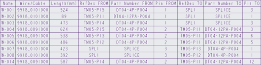
The image below displays the output in the flattened drawing.

The image below displays the output when Group From and To columns together is not selected.
Cavity Table Customizations
Draw Component View
If this option is selected, you can select the cavity view to be generated for the table. The available view orientations are FRONT, REAR, TOP, or ALL. An example of the output is shown in the figure below for the view orientation REAR.
The figure below shows cavity tables when the ALL option is selected and all three orientations are presented.
Cavity Tables are the only type of table that can have a component view. Component views require a cavity table with at least two columns to be displayed. The Draw component view checkbox is automatically cleared if the number of columns is reduced to one.
Display target information
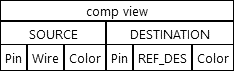
For each wire routed to a pin in a connector, information can be extracted from the other end of the wire and displayed in the cavity table. When this option is selected the current cavity table configuration is copied, and the columns are grouped into Source and Destination columns, as seen in the table preview below.
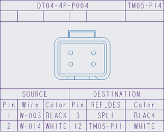
See the below example of the output in the drawing:
Consider these constraints when displaying the target information:
• The grouping names SOURCE and DESTINATION cannot be customized.
• If the default Wire/Cable name Wire column is used, the equivalent destination column is the REF_DES connector.
• After this option is selected, columns can be deleted or merged, but new columns cannot be created under this grouping.
• Set up the required cavity table columns before selecting this option.
By default, this option is not selected.
Exclude splice cavity tables
Splice tables are cavity tables created for HMX detected splices.
Use this option to exclude splice tables from the drawing. When selected, no splice tables are created, but all other connector cavity tables are still created.
By default, this option is not selected.
Exclude Single Pin Components
The Exclude single pin components can be selected to prevent the creation of cavity tables for single-pin and single-entry port connectors. Any connectors with multiple pins or multiple entry ports will still have cavity tables created.
Connectors with multiple wires routed to one pin are not considered single-pin components. |
Connectors with one entry port with multiple pin parameters are not considered single-pin components. |
By default, this option is not selected.
Display empty pins
An empty pin is as a pin that does not have any cable routing, and no terminal or seal information.
The Display empty pins option controls the output of empty pins to the cavity table.
If the option is selected, empty pins are displayed in the cavity table for the connector. If the option is not selected, empty pins are not shown in the cavity table for the connector. By default, this option is not selected.
Example:
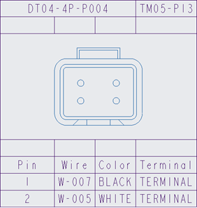
Display empty pins is selected.
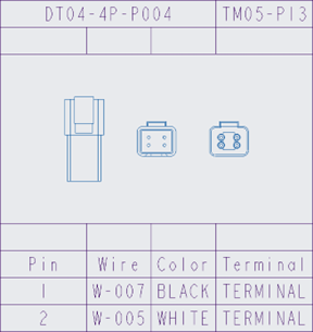
| Display empty pins is not selected.
| ||||
Build Cavity Tables as Notes
The Build cavity tables as notes option displays tables as a series of notes. An example of a Cavity table built as notes is shown next.
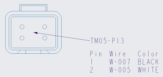
To use this option, a symbol or view is required to display the Cavity tables as notes. |
If this option is selected, the cavity tables are built as notes. If this option is not selected, the Cavity tables are built as tables. By default, this option is not selected.
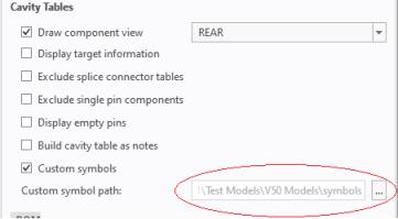
Custom Symbols in Cavity Tables
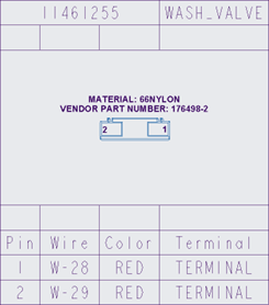
The custom symbol in the cavity table replaces the view generated by HMX with a user-defined symbol. No other functionality is affected by using custom symbols. You can define a custom cavity table, build cavity tables as notes, or use the default tables available in HMX. The figure below shows custom symbols in a cavity table.
When using custom symbols you can use these methods for retrieving the symbols in HMX.
• Store the symbols to be used in the pre-existing HMX symbol directory located in the interconnect_app folder of your Creo Parametric installation directory.
• Create a local folder directory and specify the path to the directory, as shown in the figure below.
Consider these constraints when using custom symbols in cavity tables:
• Symbols must be created in Creo Parametric and must be of the symbol definition file type (.sym). Any other file types are not supported and will be ignored.
• Symbols must be created with a fixed height. Variable height symbols are unsupported.
• When creating symbols for models, ensure that symbols comply with the following naming convention: <Part name in Creo>.sym. For example, in the above cavity table, the custom symbol was named 1080A60G12.sym.
If the Custom symbols checkbox is selected, custom symbols are used from the user input symbols directory.
If this option is not selected, the default views are used.
Bill of Materials Table Customization
Create BoM table from top down
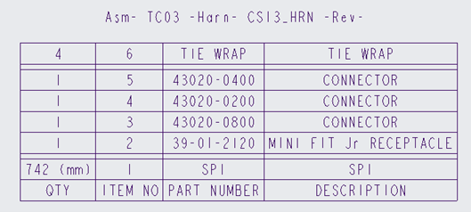
By selecting the Create BoM table from the top down option, a BoM table is created with the headings at the top of the table and with the order of items listed in reverse of the default.
An example of the default BoM table:

The same BoM table created in the reverse order:
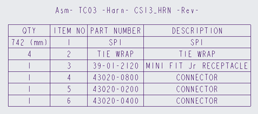
By default, this option is not selected, and BoM tables are created with the header at the bottom.
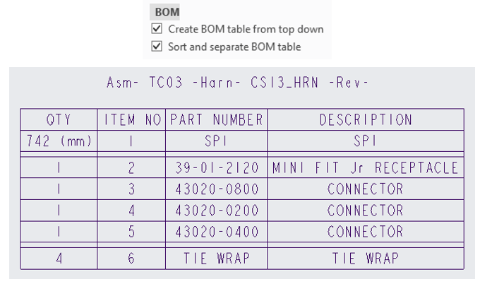
Sort and separate BoM table
If the Sort and separate BoM table option is selected, the BoM table is created with the objects in the BoM grouped by type. Groupings are separated by quarter-height empty rows.
The grouping types and their order of appearance in the sorted and separated BoM are as follows:
• Spools
• Connectors
• Seals
• Terminals
• Cosmetic items
• Bulk items
• Attached Components
An example of such a sorted and separated BoM is shown below.
The order of the groupings cannot be customized. |
A sorted and separated BoM can also be generated from the top down, by selecting both the Create BoM table from top down and Sort and separate BOM table options, as shown below.
By default, this option is not selected and the BoM tables are not sorted and separated.