Rotating Fluid Domain in Creo Simulation Live
Overview
A rotating fluid domain represents a fluid region that is solved in a rotating reference frame.
Use a rotating fluid domain when the bulk motion of the fluid is driven by rotation. Solving the flow in the rotating reference frame provides better accuracy. It is used to model fluid flow generated by internal rotating components such as fans or impellers.
When a rotating fluid domain is defined, rotating wall boundary conditions are automatically applied to all outer surfaces of the domain except those perpendicular to the axis of rotation. These rotating walls use the same angular velocity as the rotating fluid domain and are created automatically in the background.
Prerequisites for Creating a Rotating Fluid Domain
• First create a fluid study and define a fluid domain for it.
• The study must be a steady-state simulation study. Rotating fluid domains are not supported in transient mode.
• The geometry selected for the rotating fluid domain must be axisymmetric and revolve through a complete 360 degrees.
Geometry Requirements for Rotating Fluid Domains
• The selected geometry can be a solid body or a quilt.
• The entire body or quilt must be axisymmetric about a single axis of rotation. Geometry with multiple rotational axes is not supported.
• The outermost surfaces must consist of only cylindrical, conical, or spline-based revolved surfaces, or a combination of these.
Spline-based revolved surfaces are supported when they have two clearly defined adjacent surfaces.
Conical shapes are supported when they have two adjacent boundary surfaces and are not pointed at one end.
One or more coaxial cylindrical surfaces are supported.
• Each end of the body must contain only one surface whose normal direction points toward the axis of rotation.
• Internal bodies such as fans or impellers are allowed inside the rotating fluid domain as separate or cutter bodies.
The following types of geometry cannot be used as references for a rotating fluid domain:
• Bodies with cutouts or interruptions on the outer surface are not supported.
• Geometry that contains more than one axis of rotation.
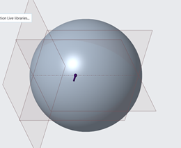
Complete spheres or ellipsoids cannot be selected as rotating fluid domains.
• Geometry that does not revolve through a full 360 degrees.
Bodies that are not axisymmetric due to cutouts or interruptions on the outer surface are not supported.
Use the following table to determine the types of geometry that can be used as references when creating a rotating fluid domain:
|
Description
|
Geometry
|
Whether Supported
|
|---|---|---|
|
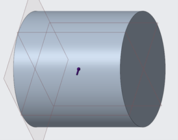
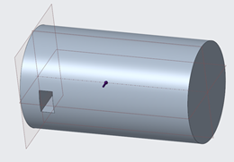
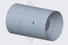
A simple cylinder is allowed.
|
 |
 |
|
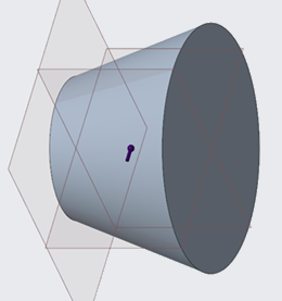
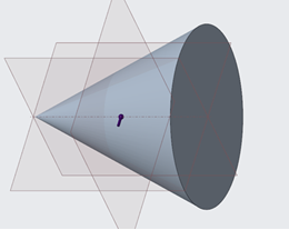
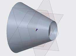
A simple cone is allowed
|
 |
|
|
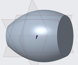
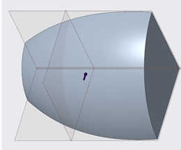
A simple spline is allowed
|
 |
|
|
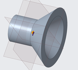
Conjugate cone-cylinders are allowed as long there is a clear separation by a planar surface between the external cones or cylinders and the internal cones or cylinders
|
 |
|
|
A pointed cone is not allowed as it does not meet the criteria of having 2 adjacent boundary surfaces.
|
 |
 |
|
A cylinder with a notch is not allowed as it is not axisymmetric.
|
 |
|
|
Incompletely revolved surfaces are not allowed.
|
 |
|
|
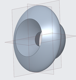
Tori and spheres are not allowed.
|
 |
|
|
A spline connected to a single planar surface is not allowed.
|
 |
|
|
An external cylinder adjacent to an internal cone is not allowed.
|
 |
|
|
An external cone adjacent to an internal cylinder is not allowed.
|
 |
|
|
A spline-based revolved surface adjacent to a cone is not allowed.
|
 |
|
Creating a Rotating Fluid Domain
1. Open the active fluid study and ensure that a fluid domain has already been defined.
2. Click Live Simulation. Click the arrow next to Boundary Conditions and select Rotating Fluid Domain to open the Rotating Fluid Domain dialog box.
3. Select a single reference body or quilt from the defined fluid domain.
4. Select the axis of rotation. The selected geometry must be coaxial to this axis.
5. Specify the angular velocity. A positive value follows the native axis direction, while a negative value reverses the direction.
6. Click OK to create the rotating fluid domain. The domain is listed under Boundary Conditions in the Model Tree.
Boundary Conditions on a Rotating Fluid Domain
• Flow velocity, inlet pressure, outlet pressure, mass flow, and swirl inlet boundary conditions can be applied only to surfaces perpendicular to the axis of rotation.
• Thermal boundary conditions can be applied to non-perpendicular surfaces of the rotating fluid domain.
• Boundary conditions applied to non-perpendicular surfaces that are not supported are silently ignored during the simulation.