Stretch a face or an edge
Creo Elements/Direct Modeling allows you to move (stretch) the faces or edges of a part, maintaining the original boundaries of the faces or the edges that are stretched. The boundaries (edges) of the stretched elements are maintained by changing the neighboring faces.
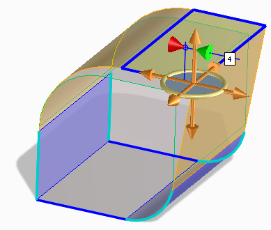
You can also stretch several unconnected faces simultaneously as shown in the following image.

To stretch a face or an edge,
1. Click Modeling and then, in the Modify 3D group, click the arrow next to  Modify.
Modify.2. Click  Stretch. The Stretch dialog box opens.
Stretch. The Stretch dialog box opens.3. Select the following:
◦ Faces: Click Faces and select a face that you want to stretch in the viewport. Press SHIFT to select multiple faces and middle-click to end the selection.
 |
You can also select a face in the viewport and click
on the Command Mini Toolbar (CMT) to stretch the face. |
◦ Edges: Click Edges and select an edge that you want to stretch in the viewport. Press SHIFT to select multiple edges and middle-click to end the selection.
 |
You cannot select multiple edges on the same face.
|
|
|
You can also select an edge in the viewport and click
 on the CMT to stretch the edge. on the CMT to stretch the edge. |
 |
When you click Edges in the Stretch dialog box, the Transform Objects check box becomes inactive.
|
4. Set the following options:
◦ Transform Objects: Allows you to position parts or assemblies without having to stretch the faces, when all faces of a part or all parts of an assembly are selected.
|
|
Draw a box to select whole parts or whole assemblies. You can also use the Select tool to select all the faces of a part or all the parts in an assembly. The highlight color of selected parts changes to dark blue. The highlight color of selected assemblies changes to cyan. You can change the default colors in Modeling Settings.
|
|
|
Transform Objects is selected by default. To change the default setting, see Change Modeling settings.
|
◦ Keep Tan: Preserve the tangential transitions between neighboring faces. Click Control to fix or unfix edges and faces. If you choose not to Keep Tan, smooth tangential transitions are replaced by edges.
|
|
Additionally, Keep Tan preserves tangential transitions between a face that is not stretched and a neighboring face (if the neighboring face is not tangential to the stretched face).
|
◦ Redo Blend: Allow the operation to make automatic adjustments to blends. Click Control to specify the blends.
◦ Position: Allow re-positioning of the face or the edge to be stretched. You can drag the 3D CoPilot in the viewport to stretch the face or the edge. See Position options.
◦ Excluded Faces: Allows you to exclude faces neighboring an element (face or an edge) that is selected for the Stretch operation.
|
|
• Select a face again to remove it from the selection.
• Middle-click to complete the selection.
|
|
|
• After you select valid excluded faces, the highlight of the corresponding fixed elements is removed.
 • An error message appears if the selected faces are not neighboring a stretched element.
|
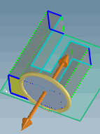
◦ Fix Elem: Allows you to change the fixed elements of the neighboring faces selected by Creo Elements/Direct Modeling. The fixed elements selected by Creo Elements/Direct Modeling are highlighted in the dark blue color. The elements that you can select as fixed elements are highlighted in the light blue color as shown in the following image.
◦ The Upd Rels option is available when the Parametrics module is active. Select this option to update relations with your changes.
5. Click Preview to see the impact of changes before accepting them.
|
|
You can toggle between Realistic and Quick to either view realistic feedback or quick feedback in the viewport when you stretch a face. See Realistic feedback.
|
6. Click Next to finish the operation and stretch another face.
|
|
You can click Chk & Fix if you suspect a part is corrupt. Chk & Fix checks for self-intersections, knife edges, and void shells and attempts to fix them. If a part fails the check and fix, it is not modified and remains in its original state.
|
7. Click  to complete the operation.
to complete the operation.Limitations
• You cannot stretch neighboring faces that have all vertices as fixed elements as shown in the following image.

• Creo Elements/Direct Modeling can change the surface types of the neighboring faces depending on the fixed edges, when it cannot retain the analytical geometry.
• If you use the Stretch command on multiple parts, the successful operations are displayed as a partial result and the failures are displayed as labels (error feedback). The feedback labels are attached to the faces on which the operation has failed.
Stretch command on multiple parts, the successful operations are displayed as a partial result and the failures are displayed as labels (error feedback). The feedback labels are attached to the faces on which the operation has failed.