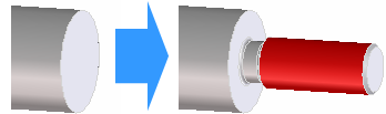
Thread undercuts are easy to add with Creo Elements/Direct Part Library. Define a threaded face first, unless you want to add the thread, chamfer, and undercut to a circular face in one step, like this:
Several standard undercut types are available:
• Type A: DIN 76 type A (normal case) is created on a shaft.
• Type B: DIN 76 type B (short form) is created on a shaft.
• Type C: DIN 76 type C (normal case) is created in a hole.
• Type D: DIN 76 type D (short form) is created in a hole.
By default, undercuts are added as user-defined features. You can change this in the Defaults dialog box. Click (dialog box launcher) in the Features group to open the Defaults dialog box.
To add an undercut to a threaded face,
1. Click Part Library and then, in the Feature group, click the arrow next to Thr. U.-cuts.
2. Click on the undercut type you want. Select a command in the Bolt and Thread Undercut section if you also want to add an outer thread and chamfer to a circular face.
3. Set the undercut dimensions and options. Please note the following:
◦ The thread pitch is taken from the thread face adjacent to the selected edge. To change it, click thread pitch and select from the list of standards.
◦ DIN standards only allow two blend angles: 30 and 60 degrees.
◦ The direction must be along the axis of the cylindrical face. You usually do not need to change this.
 (dialog box launcher) in the Features group to open the Defaults dialog box.
 Thr. U.-cuts.
 to complete the operation.