Create a helix
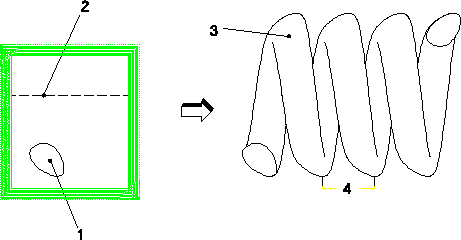
The freeform operation Helix sweeps a profile (1) about an axis (2) in order to create a helical part (3). An example of this operation is shown below.

The Preview option gives you a first impression of the shape of the part to be created. Use the Check Part function to verify the integrity of the part to be created by the sweep operation.
The following rules apply:
• The profile to be swept (1) and the sweep axis (2) should be located in the same workplane.
• The profile to be swept must not intersect the sweep axis.
To create a helix,
1. Click Modeling and then, in the Model group, click More.
2. Click  Helix Add in Helix section. The Helix dialog box opens.
 Helix Add in Helix section. The Helix dialog box opens.
3. On the Modeling tab, in the Model group, click More and then, click  Helix Remove in Helix section. The Helix dialog box opens.
 Helix Remove in Helix section. The Helix dialog box opens.
4. Select or enter a Part name.
5. Select the Workplane. All profiles on the workplane will be swept.
6. Select the Axis of the helical path along which you want to sweep the profile(s). Make sure that none of your profiles intersect this axis.
7. Set the Pitch, which is the distance by which the path of the profile rises with each additional turn about the helix axis. The pitch needs to be large enough to ensure that the helix is not self-intersecting.
8. Enter the number of Turns. This number can include decimals.
9. Set the Approx Tol if you want to control the error of approximation for the helical tolerance. Enter a helical tolerance value less than .001mm (it will toggle automatically). This will approximate the exact helix distance.
10. Set Right Hand for a right-hand orientation (like a standard screw thread). Turn this setting off if you want to create a left-hand helix.
11. Select Check Part to verify the part's integrity during the sweep operation. Although the operation is faster without this option, you may create a corrupt part. We recommend you keep the Check Part option on, because the part checker will not be able to detect that the part is corrupt.
12. Click  to complete the operation.
 to complete the operation.