Adding a lip means to add an additional sheet to an existing sheet metal part. The lip is attached to an edge of the existing part. You can add lips to multiple edges of a part at the same time.
Begin by selecting the edge to which you want to add the lip. Optionally, you can click Oppos Edge to add the lip to the opposite edge.
Optionally, define an offset for the lip. This offset is added as a rectangular section aligned with the existing sheet. The offset serves as a rectangular extension that connects the lip to the original sheet. Do not confuse this offset with the Z shaped geometry inserted by means of the Offset command.
If you want to invert the orientation of the lip profile, click Reverse Dir. Depending on the orientation of the lip profile, material is added to the side facing the existing part or away from the existing part.
Now you define the Lip Bend, Lip Shape, and Lip Bend and Corner Relief and other Lip Connections.
Lip bend
Define the lip bend as follows:
• Specify the angle of the lip with respect to the sheet to which the lip will be added.
• Select the bend process by which the lip is to be produced.
• Specify the bend radius.
Lip shape
The lip outline displayed by Creo Elements/Direct Sheet Metal indicates the shape of the lip to be created. The lip shape is controlled by:
• The lip length. Once you have specified the lip length, the associated lip profile (plus its workplane) is displayed. This lip profile provides instant visual feedback of any changes in lip shape, size and orientation.
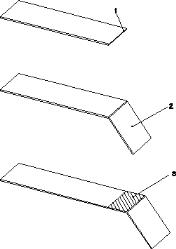
The lip length does not influence the overall length of the sheet metal part. However, any offset you specify is added to the sheet metal length. In the following figure, the length of the sheet metal part is shown in its original state (1) and after a lip has been added without an offset (2). If you specify an offset for the lip, the overall length (3) is the original length (1) plus the offset (4).
• The geometric constellation of the new lip and its "left" neighbor.
• The angle of the "left" edge of the lip.
• The distance between the lip and the "left" vertex of the new lip on the selected edge.
• The geometric constellation of the new lip and its "right" neighbor.
• The angle of the "right" edge of the lip.
• The distance between the lip and the "right" vertex of the new lip on the selected edge.
The two distances define the width of the new lip.
When you select one of the constellation options, the distance and angle fields are selected automatically to reflect the selected lip shape. Note also that selecting the lip shape by constellation type may also lead to an existing neighbor lip to be automatically changed. When this will occur for either the left or right neighboring lip or both, the appropriate L Neighb and R Neighb check boxes become active. To create the new lip without affecting the neighboring lip, clear the relevant check boxes.
Use the L AutoMiter and R AutoMiter check boxes to turn on the automatic detection of a miter situation. When the option is turned on and after a newly created lip, the system searches for a potential miter situation or existing neighbor miter lips. If either of these situations is detected, the system retrieves as many parameters as possible. With existing neighbor miter lips, all necessary parameters are retrieved automatically. In this case, you can create a new miter lip by selecting an edge.
The lip profile angle and distance can be defined in one of the following ways:
• by entering values directly
• with reference to a neighboring face
• with reference to a symmetry plane of a corner
• via corner constellations.
Click any of the angle, distance, or left/right lip buttons defining the lip shape to open the Angle / Dist dialog box, and define the parameters with one of the following options:
• Angle: This field displays the angle calculated by the other options.
• Dist: This field displays the distance calculated by the other options.
• Ref Face: Select a reference face to which the profile angle or distance should be aligned. The reference face must be planar for this operation to succeed. Profile angles are calculated in such a way that the profile is parallel to the intersection of the profile workplane and reference face.
• Corn Edg: Select two edges. The bisecting plane of the edges is taken as reference plane to which the profile angle or distance is aligned. (Hint: Use Shift-Left-Mouse button to select the list of two edges and close the list with Shift-Middle-Mouse button.) Profile angles are calculated so that the profile is parallel to the intersection of the profile workplane and a symmetry plane between the selected edges.
• Other Lip: Select the corner constellation type from the graphical list:
The green area represents the new lip to be added. (Note that this command is the same as the Left Lip and Right Lip commands in the Add Lip dialog box; it is provided there for convenience.) After you make a selection, the dialog box displays the Oth Lip Face button if there are multiple lips to choose from, which you click and specify the other lip face defining the corner constellation. If necessary, enter a Gap Dist between the lips or an Offset from the farthest face of the other lip. Note that the feedback body does not show the true modified geometry; this is effected when you click OK.
• Inner Offset or Outer Offset: When you specify the angle or distance by reference face or by corner edges, Creo Elements/Direct Sheet Metal calculates the offsets of the inner and outer edges of the lip from the selected face or implied reference plane. You can edit either of the offsets if necessary; the other offset is adjusted automatically.
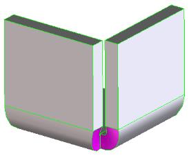
Lip bend and corner relief and other lip connections
Bend and corner reliefs are necessary to prevent any undesired material distortion during manufacturing. The type and dimensions for bend and corner reliefs are very much design dependent and can be freely chosen. It is also possible to work with spline V reliefs or with no reliefs. These are available as special relief tool types.
By default, Creo Elements/Direct Sheet Metal selects the left and right reliefs automatically. You can change these selections to one of the following relief or connection options:
None
Specifies no reliefs to be added:
Join
Cuts the faces between the base part and the lip; what replaces the faces depends on the nature of the lip. In other words, it joins the two side faces of the sheet in or near a newly created bend in the case that those side faces are not parallel or identical. This option is mainly used for new lips with a left or right profile angle to avoid unexpected steps in the sheet:
Compare the graphic with that of "None Connection" above.
Join acts as a true cut operation in that the open edges are grown, if necessary, and may meet to create a freeform face. It may also simply cut off a sharp edge, replacing it with a straight face.
CutToBend
Cuts the lip down to the bend, removing the unneeded metal above the bend area. The bend itself is unaffected:
This option is mainly used as preparation for a subsequent corner relief at that point. The following graphic demonstrates the final situation:
CutInclBend
Cuts the lip down to and including the bend, but not further affecting the base part. This option is mainly used in cases where a normal bend relief is not wanted or would be too close to the next sheet corner:
Bend R.
Specifies a bend relief.
Miter BR.
Specifies a miter bend relief. This option is selected automatically when an open corner constellation is set to the Miter option.
Corner R.
Specifies a corner relief.
If you select Bend R., Miter BR., or Corner R., you can click Left or Right to open a Left Relief or Right Relief dialog box in which you can further specify the relief type, as follows:
1. Click the option list next to Type and select one of the punch tools suited for bend or corner reliefs.
2. Creo Elements/Direct Sheet Metal displays a table containing the available punch tools of the set type; select one and click Apply. The relevant relief value is displayed in the Tool Dim box.
3. For bend reliefs, enter also the relief depth.
• The original sheet metal part (1).
• The same part with an added lip (2).
• The same part with an offset (3) between the added lip and the original sheet.
When you add a lip to an edge which has a bend at one or both of its ends, the "straight" segment of the edge defines the lip width. Creo Elements/Direct Sheet Metal automatically places a bend relief where required. This process is illustrated in the following figure.
The original length of the straight edge segment (1) defines the lip width (2). A bend relief (3) is automatically inserted at the bend (4).
Example: Adding a lip
In this example you will add a lip to an existing sheet metal part.
1. Click Sheet Metal and then, in the Model Sheet group, click Lip. The Add Lip dialog box opens.
2. Click an edge (1) on the sheet metal part.
3. Click Offset and enter an offset length (2). Creo Elements/Direct Sheet Metal provides a quick preview of the lip offset.
4. In the Lip Length box enter a lip length (3). Creo Elements/Direct Sheet Metal displays a workplane containing the lip profile.
5. In the Left Angle box enter an angle (for example 80). Note that the left border of the lip profile adjusts to reflect the angle.
6. In the Left Dist box enter a length (4). Note that the left edge of the lip outline moves in from the left.
7. Click Right Angle and enter an angle (for example 120).
8. Click Right Dist and enter a length (5).
9. Click Bend Angle and enter an angle (for example 72).
10. Click Process and select Bend Folding.
11. Retain the defaults for the bend folding radius and the bend relief.
12. Click Preview to preview the sheet metal part with the lip.
13. Click .
The specified lip is attached to the sheet metal part.
If you enter a bend angle for which there is no tool or allowance value in the TDB, Creo Elements/Direct Sheet Metal prompts you with a warning. Based on the message Creo Elements/Direct Sheet Metal issues, you can decide to continue (click Continue) or enter a new angle (click Cancel).


 Lip. The Add Lip dialog box opens.
 .
.