Creo Elements/Direct Modeling IDF Data Adapter (PCB I/F) Basics
Terminology
PCB Assembly
A printed circuit board assembly including all profiles, parts and subassemblies contained in it.
PCA
This is a (shorter) synonym for PCB assembly.
Part
A shared instance of a model representing an EE component in a PCB assembly.
Model
A 3D mechanical representation of a part. Creo Elements/Direct Modeling IDF Data Adapter (PCB I/F) provides special functionality for creating such models. These models can be retrieved individually or collectively from predefined as well as customized libraries.
PCB Profile
In Creo Elements/Direct Modeling IDF Data Adapter (PCB I/F), profiles serve as media for importing 2D information to Creo Elements/Direct Modeling and for exporting the relevant geometrical information of PCB assemblies to an EE file format. This information includes the board geometry.
Structural concepts for PCB assemblies
This section provides information on the structural concepts used in the IDF Data Adapter (PCB I/F). Be sure to understand these concepts before you start using the adapter.
The IDF Data Adapter (PCB I/F) creates and requires a specific part and assembly structure for proper operation. The following figure depicts the basic structure of a PCB assembly:
The structure currently shows the active PCB assembly with an underline (or highlight, according to your setting).
If you have multiple PCB assemblies in the Creo Elements/Direct Modeling Structure Browser, you can right-click the PCB assembly and choose Set Active from the context menu, to make the PCB assembly active.
Most of the PCB I/F commands (on the PCB tab) like the Part commands (in the Part group), the Model commands (in the Model group), and the Profile commands (in the Profile group) work only on the active PCB assembly.
You must keep the following in mind while creating a PCB assembly:
• You can create a PCB assembly at the root (/) level, or as the child of an assembly.
• You can create multiple independent PCB assemblies in a Creo Elements/Direct Modeling session. Each PCB assembly has its own separate structure and owner. One PCB assembly cannot be the owner of another PCB assembly.
• When you create a PCB assembly, you must click the PCB tab and then, in the Model group, click Update to view the workplanes at the correct location. For example, the initial location of the profile workplane is in the XY plane (Z=0) in the local coordinates of the PCB assembly, the Board-Outline profile workplane is at a height equal to half of the board thickness, and the Drilled-Holes profile workplane is always at the origin of the PCB assembly.
• Each PCB assembly must contain the following items:
◦ LIB_CONT: This container holds the local library of the component models (in the LIB_PART assembly) and any associated profile workplanes (in the LIB_PROF assembly).
◦ PROF: This container holds the 2D PCB profile workplanes that define the PCB assemblies. Some examples of the PCB profile workplanes are board blank outline, cutouts, drilled holes, keepouts, and restrictions. The 3D model of the PCB is automatically created by extruding and (or) punching these 2D profile workplanes. When you export a PCB assembly, the geometry on the 2D profile workplanes is exported to the ECAD format.
◦ RESTR: This container holds the 3D representations of the keepouts or the restricted areas. These areas are represented by thin red planes.
◦ PARTS: This assembly holds the actual 3D representation of the PCB assembly. It consists of the board blank (BOARD_PART) and the shared instances of the models from the LIB_PART assembly that are placed on the board.
Structural concepts for imported PCB assemblies
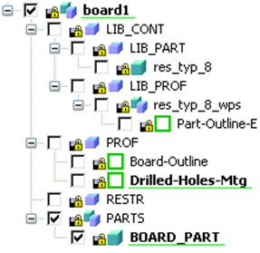
You can use the Import command to import a PCB assembly. For example, you can import a PCB assembly from the ECAD format. The following figure depicts the structure of an imported PCB assembly.
• Each component model in the LIB_PART (local library) has a corresponding set of profile workplanes in the LIB_PROF container. These profile workplanes can contain model outline data but also pin and mounting hole data. For example, for the res_typ_8 model, the profile workplanes are in the res_typ_8_wps subassembly.
• The PROF assembly holds the 2D workplanes that are imported from the ECAD format. Each workplane is used for a specific purpose. For example, the Board-Outline workplane is used to extrude the 3D representation of the BOARD_PART (board blank), the Drilled-Holes-Tool workplane contains profiles for tooling holes which are punched through the board blank, and the Place-Keepout-Top workplane contains geometry representing the keepouts or restricted areas.
• The RESTR assembly holds the 3D representation of the keepouts or restricted areas. These areas are represented by thin red planes. Height-restricted keepout workplanes are placed at the correct height on the surface of the PCB.
The thin keepouts are extruded from the corresponding profile workplanes to a customized thickness. This thickness is uniformly distributed above and below the surface of the board blank. Thus the value of the actual clearance distance is half of the thickness value which you have defined.
You must keep the following in mind while importing a PCB assembly:
• If you configure a local file-based library or Creo Elements/DirectModel Manager library for PCB I/F components, the Import process loads 3D component models. In most cases the imported models are more detailed and accurate.
• The component models in a PCB assembly which is imported from the ECAD format are extruded ("block") type.
• When you do an Update operation on the imported PCB assembly, the workplanes are automatically visible at the correct location.

 Update to view the workplanes at the correct location. For example, the initial location of the profile workplane is in the XY plane (Z=0) in the local coordinates of the PCB assembly, the Board-Outline profile workplane is at a height equal to half of the board thickness, and the Drilled-Holes profile workplane is always at the origin of the PCB assembly.