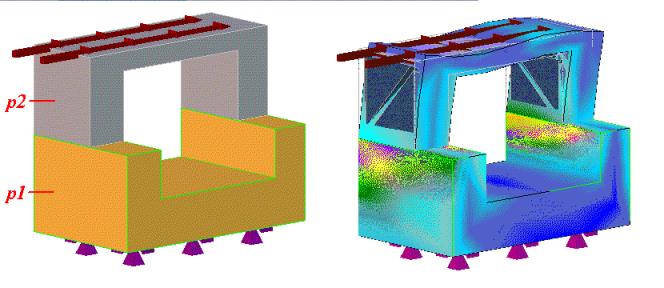
An FE analysis can also be performed on parts within an assembly. The parts must be physically touching one another (mated together) in order to transmit the applied loads. These parts can be of different materials. This feature is particularly useful when working with assemblies where the material properties of parts are different. The figure shows the effect of forces applied to two alloys mated together.
When analyzing assemblies, note the following:
• The parts to be analyzed must be in an assembly.
• The study is owned by the assembly (not one of the parts).
To analyze parts within an assembly,
1. Create the assembly a1 containing parts p1 and p2 as shown in the figure below.
2. Make sure the faces are mated together (use Mate Align).
3. Create a study (make sure the owner of the study is the assembly.
4. Assign a material to part p1 (for example, steel).
5. Assign a material to part p2 (for example, aluminum).
6. Create a face constraint on p1 (click Constraints in the Mechanical LBC group).
7. Create a face load on p2 (click Loads in the Mechanical LBC group).
8. Click Mate Reltn in the Mechanical LBC group to display the Mating Relation dialog box.
9. Click face 1 to specify the reference face.
10. Click face 2 to specify the related face (use the Structure Browser to hide p1 and then rotate p2).
11. Click Next and repeat the above with the remaining faces.
12. Click to close the Mating Relation dialog box.
You can now analyze the design in the usual manner (Analyze, Define Job, specify the required results).
 to close the Mating Relation dialog box.