Once you have defined the constraints, loads, and enforced displacements on the design model you can start the automatic mesh generation by itself or start a combination mesh generation and analysis run (available only in Creo Elements/Direct Finite Element Analysis).
The unconditioned mesh generated by the AutoMesh button can be a good starting point for mesh refinement. By viewing the unconditioned mesh you can decide whether or not to apply certain mesh conditions, choose critical areas of the model for mesh refinement, and evaluate the positioning of loads and boundary conditions.
The following figure shows the design for a plastic connector after automatic mesh generation without applying any user-defined mesh conditioning.
To create a mesh using AutoMesh,
1. Click Modify and then, in the Mesh group, click AutoMesh
The AutoMesh dialog box opens, with any current study automatically available in the Study box.
If there is no current study, or if you wish to select a different one, specify the name of the study in the Study box.
2. Click Part and specify the part you want to mesh in one of the following ways:
◦ Click the part.
◦ Select the part from the Structure Browser.
◦ Use the Select tool.
◦ Type the name of the part in the Part box.
◦ Type the name of the part in the user input line including double quotes and the path name. For example, "/mypart1".
3. Select any desired sub-options. The following sub-options are available:
◦ Global ElemSize (Element Size) allows you to specify the size of the elements used to create the mesh.
When you select a part as described above, Creo Elements/Direct Finite Element Analysis calculates an average default element size to use for meshing the part based on the dimensions of the geometry. This value is displayed in the Global ElemSize box.
You can accept this value or enter a new element size in the Global ElemSize box.
◦ Elem Order (Element Order) allows you to select:
▪ Linear: Creates elements with nodes only at the element vertices. Use Linear elements only for a quick first impression of the structural situation. For more accurate results always use quadratic elements.
▪ Quadratic: Increases the number of nodes per element. Additional nodes are at the midpoints of the lines connecting the element vertices. In most cases, a quadratic element order improves the accuracy of the results but requires more processing time by the solver. (This is the default.)
▪ P-Elements: Increases the order of the polynomial that interpolates
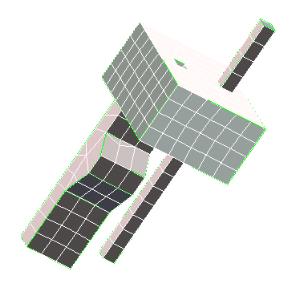
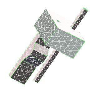
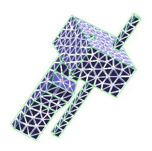
◦ Elem Shape (Element Shape) allows you to select the shape of the finite elements used to construct the mesh (see the graphics below). The choices are: functions within the element.
▪ Solid:Tetra (default) - Solid tetrahedral elements; that is, a solid mesh consisting of regular bodies having four triangular faces.
▪ Surface:Triad - Triangular surface elements; that is, a surface mesh consisting of triangles. If you're not certain which surface element shape to use, select Surface:Triad.
▪ Surface:Quad - Quadrilateral surface elements; that is, a surface mesh consisting of four-sided elements.
4. Click to accept the entries and start the mesh generation.
A quadrilateral surface mesh is in reality a "quadrilateral-dominant" mesh. In some cases, it is necessary to insert triangular elements into a quadrilateral mesh to meet the geometry situation or criteria for mesh quality.
You can export surface meshes using the Mesh button in the Output group for use in third party FEA applications.

 to accept the entries and start the mesh generation.