Creo Elements/Direct Cabling Tutorial 1: Step 2 of 4
Run a library
Creo Elements/Direct Cabling parts, such as connectors and cables, are organized into libraries. The module comes with some default libraries, and you can create your own parts to build custom libraries. You will run a standard library for this exercise. You can learn how to create your own library in a later tutorial.
To run a connector library,
1. Click Interface and then, in the Library group, click the arrow next to Call, click Call connector library. The Cabling Electrical Library opens.
2. Click Demo.
3. Click 1200712 from the Demo dialog, which looks like this:
The E-Lib Component dialog box opens.
Position a connector
Two positioning options are available: Free or Snap-in. Use the Snap-in positioning option to place a connector into a mating connector. You will use the Free positioning option.
To place a connector,
1. Click Free in the Position section of the E-Lib Component dialog box.
2. Define the Origin: Click on point A of the sheet metal part, as shown:
3. Define Direction Z: If you select a face for the origin, the default Z direction is perpendicular to the face. You can change the direction, but you want the default for this exercise.
4. Define Direction X: Select the edge shown at B in the image above.
5. If a long side of the connector does not face the wall of the sheet metal part, click Rot 90 to rotate the part until it faces the proper direction.
6. Click Position in the Reposition part section of the E-Lib Component dialog box. The Position dialog box open.
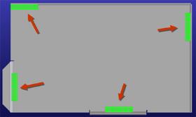
7. Use the Position dialog box to move the part against the wall and left edge of the sheet metal part, as shown:
8. Click OK to complete the operation.
9. Add three more connectors so that your assembly looks like this:
 Call, click
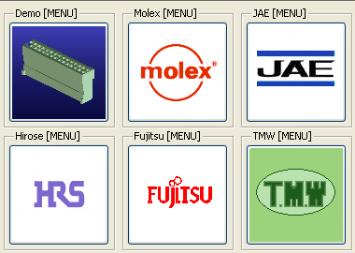


 to complete the operation.