The Point 3D CoPilot is activated in the 3D curve commands. The Point 3D CoPilot appears on the screen with a local coordinate system shown by 3 arrows (U, V, and W) and 3 planes (UV, VW, and WU).
The Point 3D CoPilot operates in two modes: 3D Pick and Plane - UV Plane, VW Plane, WU Plane. Right-click to switch the mode.
3D pick mode
In 3D Pick mode, the Point 3D CoPilot catches to existing geometry elements.
If there is no existing geometry, the behavior of the tool depends on the visibility of the workplane.
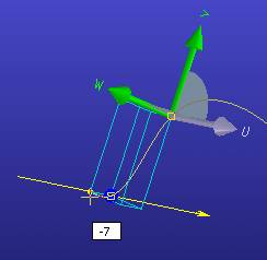
• Active workplane is visible: The current cursor position is projected onto the workplane's (0,0) point. Rectangular feedback indicates the position of the workplane and the position of the 3D point.
• Active workplane is not visible: The current cursor position is projected onto a virtual plane through the Point 3D CoPilot's origin and normal to the viewport direction. Rectangular feedback always starts at the Point 3D CoPilot's origin.
Plane mode
The options for plane mode are UV, VW, WU.
Switch from 3D Pick mode to plane mode by clicking on an arc between two axes or right-click and select the plane from the context menu. The arc disappears and the associated CoPilot arrows become green. The Point 3D CoPilot now behaves like the 2D CoPilot on the chosen plane.
Right-click the Status Bar and click 2D Position on the context menu. When you move the cursor in the viewport, the 2D coordinates are displayed on the Status Bar.
Click points on your model or in the workplane. The 3D Projecting option from the 2D CoPilot is available. Vertices and edges can be projected temporarily onto the active plane by hovering over these elements with the cursor. Feedback is drawn as a catchable element in the active plane. When the cursor approaches one of these catchable elements, the feedback snaps to that element. Click to use the position of that element as a 3D point. See
2D CoPilot overview documentation for details.
Lift Point - In plane mode, define an offset for the interpolation point in relation to the active plane.
1. Select Lift Point from the context menu. A dragger appears at the current cursor position.
2. When you move the mouse the offset is displayed near the cursor. Feedback in the form of a 3D box shows the base point in the active plane and the lift point's position with respect to the active plane.
3. Drag the mouse and align the point's position with existing geometry. When the cursor is on an element that is parallel to the active plane or on a vertex, the point snaps to the same height as that element. Deactivate the snapping capability by holding down the Shift key while dragging.
View by Active Plane: Available in plane mode. While creating points, change the view so that the current plane is shown.
Coordinate type: You can choose between Cartesian Coordinates and Polar Coordinates by right-clicking in the viewport. These options are only available while you are in a plane mode.
Enter coordinates: Right-click and select Freeze Coordinates to type coordinates into the dialog on the right.
2D CoPilot Settings: Modify the 2D CoPilot settings. See
Change 2D CoPilot settings documentation for details.
Clear 3D Projected Geometry: In plane mode, clear the temporary projections of elements that appear in the active plane.
Repositioning
The initial position of the Point 3D CoPilot is determined by the current command. This position may be the origin of the global or local coordinate system or a previously-defined point.
Reposition the Point 3D CoPilot:
• Position Dynamic: The
3D CoPilot appears. Click the 3D CoPilot and move the mouse to reposition the Point 3D CoPilot. To redefine the origin, click the blue sphere and click a new position. See
3D CoPilot features documentation for details.
• Define Origin: Click on a new position to redefine the Point 3D CoPilot's origin.
• Define W-Axis: Redefine the W axis with the
Direction 3D CoPilot. The U and V axes are rotated accordingly. The origin is not changed.
• Define U-Axis:: Redefine the U axis with the
Direction 3D CoPilot. The W axis will not be modified. The U axis will be aligned with the new direction. The V axis will be rotated accordingly. The origin is not changed. You must define the W axis before defining the U axis or the U axis will be modified to fit the W axis definition.