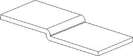
Inserting an offset, or a Z-fold, means to integrate a step into an existing sheet metal part. The graphic below shows an example:
To insert an offset you click an edge which must be normal to the intended offset. Then you specify a split point to position the offset and click the area of the sheet you want to rise. Finally you specify the offset height.
The offset height is measured from the top of the sheet area that is offset to the top of the sheet area that remains in its original position.
The specified split point, designating the offset across the part, lies at the edge of the offset fold line.
The offset bend radius is calculated as follows:
• If the offset height is less than or equal to the thickness, both inner radii are set to height/2 and both outer radii are set to height/2.
• If the offset height is greater than the thickness, both inner radii are set to (height - thickness)/2 and both outer radii are set to (height + thickness)/2.
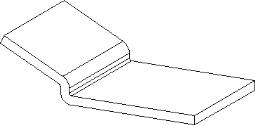
The area of the sheet that does not move stays parallel to the area of the sheet that has been offset. To create an unrestricted offset (shown in the following graphic), use the Polyline commands.
Keep the following in mind when creating offsets:
• Offsets cannot be created through holes or stamps. You can use Creo Elements/Direct Modeling machining commands to punch through the bend after the offset has been made.
• If the bending allowance for an offset is not specified in the TDB, the flat generation uses the shop-wide fall-back formula in the shop definition. For details, refer to Creo Elements/Direct Sheet Metal
Creo Elements/Direct Sheet Metal shop changes.
However, this may give inaccurate results in some cases because the outer radius is not equal to the inner radius plus sheet thickness.
• The edges of the sheet that are connected by the offset must be parallel.
Example: Inserting an offset
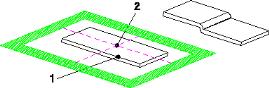
In this example you will insert an offset into an existing sheet metal part. Shown below are the existing and the resulting part:
1. Click Sheet Metal and then, in the Model Sheet group, click Offset. The Insert Offset dialog box opens.
2. Click an edge (1) normal to the intended offset.
3. Specify a point (2) to position the offset.
Use a workplane and construction geometry to define an exact position for the offset.
4. Click the area of the sheet face you want to rise.
5. Specify a bend process or accept the default. Default is the Offsets process.
6. Specify the offset Height; for example, 5.
7. Click .
Creo Elements/Direct Sheet Metal inserts the specified offset into the sheet metal part.
 Offset. The Insert Offset dialog box opens.
 .
.