Every sheet metal design starts with the decision for a certain manufacturing shop and a specific material. Then you go on with creating a basic sheet metal part. You must first use a workplane and create the 2D geometry which defines the exact contours of the new basic sheet. Then you use one of the New by buttons in the Model Sheet group to create the sheet.
Which of the New by buttons you use depends on the 2D geometry you started with. You can create sheets by using a polyline, which is a string of connected lines, or you use a closed outline. The closed outline must be a valid Creo Elements/Direct Modeling profile. You can also create sheets by connecting two parallel profiles or loops.
Create a sheet metal part by its outline
To create a new sheet metal part by its outline you must first create a 2D profile. You can use any profile shape, as long as it is valid.
To be valid, a 2D profile must be closed and must not contain any overlaps. For further details see the Creo Elements/Direct Modeling Concepts Guide.
Additionally you must specify a material and a part name or accept the default.
The direction in which the sheet is created can be toggled with the button Reverse Dir.
To create multiple new sheets, first create multiple separate profiles on the same workplane. Each profile can have a unique shape. Each sheet created is a separate part and receives a unique part name. These sheets are all made of the same material and thickness.
Only sheets created with Creo Elements/Direct Sheet Metal contain Creo Elements/Direct Sheet Metal attributes. Regular parts (for example, thin-walled plates) created in Creo Elements/Direct Modeling do not contain this information.
To view the Creo Elements/Direct Sheet Metal attributes use the Inquire buttons in the Post Process group.
Example: To create a sheet with a rectangular outline
1. Make sure you have an active workplane.
2. Click Modeling and then, in the Draw group, click the arrow next to Rectangle.
3. Click Rectangle.
4. Click a point in the workplane for the start location of the rectangle. The feedback shows you the size of the rectangle.
5. Click a point in the workplane for the end location of the rectangle. To create a rectangle, you can also enter the corner points of the rectangle (for example 0,0 50,100) in the command line.
6. Click Sheet Metal and then, in the Model Sheet group, click the arrow next to New by.
7. Click Outline. The New sheet by Outline dialog box opens.
8. Specify a part name or accept the default. Default is the active part.
9. Specify the workplane or accept the default. Default is the active workplane if it contains a valid profile. All profiles on the workplane are selected.
10. If required, click Selected to choose specific profiles on the workplane.
11. Specify a material from the Sheet Metals table or accept the default. Default is the material set in the Shop Based Settings dialog box.
12. Click the 3D CoPilot and drag it to set the thickness of the sheet. The visual feedback indicates the thickness. Alternatively, you can type a value for the thickness.
You can only set thickness values that are available for the selected material. If you type a value, it is corrected to the closest available thickness for the selected material.
13. Click .
Creo Elements/Direct Sheet Metal creates a new sheet part from the rectangular profile.
If you click Selected, the Select dialog box opens. Select the profiles and click End.
Create a sheet metal part by a polyline
To create a new sheet metal part by a polyline you must first create an unclosed contour consisting of one or more 2D linear elements, which "represent" the side view of the sheet metal part.
With By Polyline you can create only one part at a time.
You cannot use splines, arcs, and ellipses as polyline. Use straight lines only and specify the bend radius to create the desired shape.
If the polyline results in a sheet metal part with multiple bends, Creo Elements/Direct Sheet Metal uses the specified bend radius for all folds created in the part at this time.
You can change the bend radius later, if desired.
Additionally you must specify a material and a part name or accept the default.
The direction in which the sheet is created can be toggled with the button Reverse Dir.
Only sheets created with Creo Elements/Direct Sheet Metal contain Creo Elements/Direct Sheet Metal attributes. Regular parts (for example, thin-walled plates) created in Creo Elements/Direct Modeling do not contain this information.
To view the Creo Elements/Direct Sheet Metal attributes use the Inquire buttons in the Post Process group.
Example: To create a sheet by a polyline
1. Click Modeling and then, in the Draw group, click Line/Arc.
2. Create an unclosed contour by selecting the points 1 - 6 as shown in the graphic below. Choose your own dimensions. The 2D CoPilot guides you with feedback for length and angle.
3. Click Sheet Metal and then, in the Model Sheet group, click the arrow next to New by.
4. Click Polyline. The New sheet by Polyline dialog box opens.
5. Specify a part name or accept the default. Default is the active part.
6. Specify the workplane or accept the default. Default is the active workplane if it contains a valid polyline.
7. Specify a Material from the Sheet Metals table or accept the default. Default is the material set in the Shop Based Settings dialog box.
8. Specify a bend process, for example Air Bending. Default is the process set in the Settings menu.
9. Specify a bend radius or accept the default. Default is the bend radius set in the Shop Based Settings dialog box.
10. Click Side.
11. Click point 7 in the graphic above to specify the material side. Click anywhere to the right of the polyline's last section. The feedback line indicates the material side relative to the last polyline section.
12. Specify the sheet length (for example 100).
13. Click .
Creo Elements/Direct Sheet Metal creates a new 3D sheet metal part, consisting of a series of connected sheets.
Create a sheet metal part by a solid
You can define a sheet metal part by solid, by multiple selections of bends, cuts and open faces on a given sharp-edged kernel block.
Example: To create a sheet by a solid
1. Create a solid block.
a. Create a 2D rectangle.
b. Extrude the rectangle to a solid block.
2. Click Sheet Metal and then, in the Model Sheet group, click the arrow next to New by.
3. Click Solid. The New sheet by Solid dialog box opens.
4. Select an edge on the block. This will highlight the two faces that share this edge.
Connect is the default setting and will normally be used when making sheets with bends.
Temporary labels, that indicate the state of the edges, are displayed. The abbreviated labels and their meanings follow:
Label
Meaning
NE
Neighbor Edge
TU
Tangential Unused Edge
MU
Miter (edge) Unused
UN
Unused Edge
BO
Border Edge
TE
Tangential Edge
TB
Tangential Border Edge
M D={1}
Miter Edges with D=miter gap distance
R={1}
Neighbor Bend Edges with R=bend radius
C D={1}
Cut Edges with D=distance of cut
TN
Tangential Neighbor Edge
NM
Neighbor Miter Edge
MB
Miter Border Edge
5. Select another edge to highlight more faces. Solid can select multiple edges at a time on a part to create the sheet metal part.
6. Click .
Creo Elements/Direct Sheet Metal creates a new 3D sheet metal part.
Options specific to Solid include:
• Cut replaces an existing bend edge by a cut edge and divides the selected part into two parts. Cut-Gap defines the cut-gap.
• Single Sheet creates a single sheet of metal without bends.
• Create Miter creates a miter edge.
• Neighb Bend defines bends of neighbor parts.
• Neighb Edge defines a neighbor edge of a part that is not defined together with the actual part(s).
• Is Inside defines the selected faces as inside or outside hull of the selected part.
• Auto Nghb switches ON (default) or OFF the automatic detection of neighbour edges and bends.
Create a sheet metal part by connecting profiles
You can create a sheet metal part by connecting two parallel planar profiles or loops. The profiles can be 2D edges on workplanes or can be taken from a 3D part.
Valid profiles or loops must fulfill the following criteria:
• All edges must lie on a plane.
• The profiles or loops must be parallel.
• The profiles or loops must be closed.
• The edges should be convex.
The following figure illustrates how the sheet metal part is created.
Example: To create a sheet by connecting profiles
1. Make sure you have an active workplane.
2. Click Modeling and then, using the Draw group, create the first profile.
3. Using the New group, create a parallel workplane.
4. Using the Draw group, create the second profile.
5. Click Sheet Metal and then, in the Model Sheet group, click the arrow next to New by.
6. Click Connect. The New sheet by Connect dialog box opens.
7. Click From and select an edge of the first profile.
Creo Elements/Direct Sheet Metal identifies the profile after you have selected the edge. If the profile cannot be identified (for example, for an edge with two adjacent planar faces on a 3D part), you must select a Face.
8. Click To and select an edge of the second profile. Select a Face if required.
9. Specify a Material from the Sheet Metals table or accept the default value. The default value is the material set in the Shop Based Settings dialog box.
10. In the Corner Radius box, specify a value or accept the default value. If a profile contains a sharp corner, Creo Elements/Direct Sheet Metal rounds the sharp corner to a fillet using the corner radius.
11. In the Number Bends box, specify a value or accept the default value. Creo Elements/Direct Sheet Metal creates the sheet metal part with the specified number of bends.
12. Specify a bend process, for example Bend Folding, or accept the default value. You can set the default value using the sha-set-default-connect-bend-process function in the sha_demoshop.lsp file which is located in Creo Elements\Direct Modeling [Version]\personality\sd_customize\SheetAdvisor\.
13. Specify a bend radius or accept the default value. You can set the default value using the sha-set-default-connect-bend-radius function in the sha_demoshop.lsp file which is located in Creo Elements\Direct Modeling [Version]\personality\sd_customize\SheetAdvisor\.
14. Click Preview to preview the sheet metal part.
 New by buttons in the Model Sheet group to create the sheet.
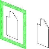
 Inquire
 Rectangle
 .
. Line/Arc
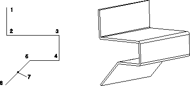
 Polyline
 Solid
Solid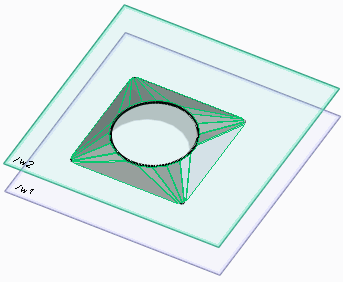
 Connect