Bend reliefs are necessary to prevent any undesired material distortion during manufacturing. The type and dimensions of bend reliefs are very much design dependent and can be freely chosen.
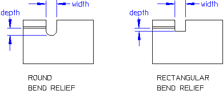
The graphic shows how the dimension's width and depth relate to the various relief types.
To create a bend relief,
1. Click Sheet Metal and then, in the Model Sheet group, click the arrow next to Relief.
2. Click Bend. The Bend Relief dialog box opens.
3. If necessary, change any of the selections in the menu as follows:
◦ Enter the name of the Part to which you want to add the relief.
◦ Enter the name of the Workplane which will hold the relief tool. The workplane must be on the face to which the relief will be added.
◦ Select the relief tool type in the Tool Type box.
Creo Elements/Direct Sheet Metal opens the relevant tool table.
4. Select the specific relief tool from the tool table, and click Apply. (You can also double-click the entry.) Creo Elements/Direct Sheet Metal attaches the tool feedback at its default reference point to the cursor. In case of round tools the default reference point is the tool center.
5. If necessary, enter an Angle on the relief tool position.
6. If necessary, change the tool's cursor adjust point.
7. Click the position where you want the relief to appear. The tool stays attached to the cursor; you can position it as often as you want.
8. Three options help you control relief creation:
◦ To remove a mispositioned tool click Pos Back. Each clicking of Pos Back removes one further tool position.
◦ Clicking Next Relief applies the positioned reliefs without ending the operation. You stay in the routine, ready to place another tool.
◦ To remove a relief that has already been applied, click Relief Back. Each click removes the reliefs created by the previous operation.
 Relief.
 .
.