You can create bends from a sharp edge or from a flat sheet at any time using the Bend button in the Modify Sheet group. The following illustration shows a simple 90 degree bend:
To create a bend,
1. Create a 2D line where you want the bend to be. (Position a workplane on the sheet's face, and use the buttons in the Draw group of the Modeling tab to this.)
2. Click Sheet Metal and then, in the Modify Sheet group, click the arrow next to Bend.
3. Click Create. The Create Bend dialog box opens.
4. Click the Face where the bend is to be placed.
5. Click the Lines along which the bend is to be formed.
6. Specify the part of the sheet (the Anchor Pt) that is to be held while the other part of the sheet is folded. (What you are doing here is defining a 3D point that does not change when using Next.)
7. Specify the relative position of the bend as shown in the image below.
8. Specify the bend attributes under Bend Attributes:
◦ Angle: The angle of the bend relative to the defining face.
9. If necessary, click Reverse to reverse the bend direction.
10. Click Preview to preview the bend or click .
11. Click Next to retain the bend attribute settings in the dialog box and continue bending parts.
12. Click to complete the operation.
You can also convert a sharp edge between two sheets to a bend. In the Create Bend dialog box, click Edge and click the edge to be replaced by a bend. Then specify the bend process and inner bend radius as above.
When creating bends, note the following points:
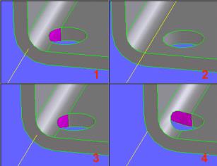
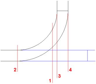
• Bend Pos specifies the positioning of the bend relative to the specifying line.
1. Centered
2. Bend Start
3. Inside
4. Outside
• Although option Centered (1) and Inside (3) look similar, they are not; as can be seen from the following:
• The default is centered.
• Bending along infinite construction geometry:
• Bending is done at all points on the face along the construction geometry even if the construction geometry appears to be of finite length.
• Bending along real geometry:
• Use the Select button in the Utilities group to select several bend lines. Note that the 2D geometry does not need to completely traverse the face. It needs only to lie on part of the face.
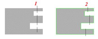
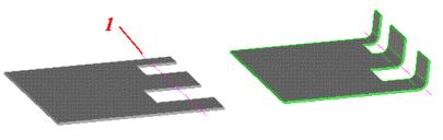
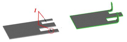
• Multiple bend lines must belong to the same infinite line:
• Bending together in figure 1 is possible. In figure 2, it is not.
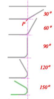
• For bend angles less than 90 degree, the projection line passes through point P. For bend angles greater than 90 degree the point of curvature passes through the vertical projection of P.
 Bend button in the Modify Sheet group. The following illustration shows a simple 90 degree bend:
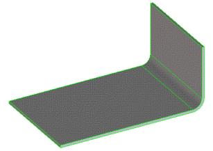
 .
.
 Select