Symmetry type relations are used to keep parts and faces symmetric about a plane of symmetry.
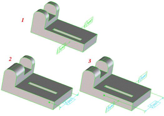
Key to figure:
1. Original part before modification.
2. Symmetry relation not defined.
3. Symmetry relation defined and distance relation modified.
You can specify the following options:
• Element 1: First reference element.
• Element 2: Second reference element.
• Sym Plane: Specify Auto to tell Creo Elements/Direct Modeling to automatically calculate the symmetry plane based on the positions of elements 1 and 2. If the model is non-symmetric, specify User and define the symmetry plane. The Auto symmetry plane is kept fixed for the relation-set update.
• Recompute: Following a modification of the model, it may be necessary to recalculate the position of the symmetry plane. To do this, click Recompute.
• Plane: This button appears only when Sym Plane is set to User. Use it to specify a planar reference element that is to be used as the symmetry plane.
• Pairs: Use the following to specify additional pairs of reference elements using the same symmetry plane:
◦ Find Pair. Specify one further reference element and Creo Elements/Direct Modeling automatically finds the corresponding partner by searching for a reference that is already symmetric relative to the symmetry plane. Both reference elements belonging to the pair are highlighted.
◦ Add Pair. Specify both references of a new symmetry pair. These references do not need to be symmetric.
◦ Find All. Creo Elements/Direct Modeling finds all pairs in the model that are symmetric to the specified symmetry plane and highlights them.
• Remove Pairs: Removes a symmetric reference pair created with the Create & Modify command. You need only specify one of the pair because Creo Elements/Direct Modeling finds and removes the other reference.