The reference element orientation options available are dependent on the type of relation being defined. Whether or not they are active depends on the types of elements specified.
The following options may be available when you create or modify a relation:
Normals is available for Distance, Parallel, Coincident and Tangent Relations.
If Normals is active and you wish to change the displayed option:
Valid Normals values are:
• Same Dir - The normals to both reference elements are in the same direction.
• Opp Dirs - The normals to the reference elements are in opposite directions.
• Open - The system chooses the option that causes the minimum components movement.
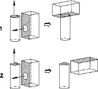
The image below shows the application of a coincident relation to a simple assembly. The selected reference elements, which are both planar, are shaded and their normal directions are indicated by the arrows.
Example 1 shows the solution with Normals set to Opp Dirs.
Example 2 shows the solution with Normals set to Same Dir.
Examples: Normals Option Use
Displacement options
Displacement is available for distance relations.
If Displacement is active and you wish to change the displayed option:
• Click in the Displacement field to display an expanded list of options.
Valid Displacement values are:
• Positive - The second reference element is in front of the first, relative to the normal direction of the first reference element.
• Negative - The second reference element is behind the first, relative to the normal direction of the first reference element.
• Open - The system chooses the option that causes the minimum component movement.
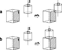
The image below shows the application of a Distance relation to a simple assembly. The selected reference elements are a planar face (1), the first selected, and a cylinder with an axis Focus (2).
Example a shows the solution with Displacement set to Positive.
Example b shows the solution with Displacement set to Negative.
Examples: Displacement Option Use
Direction options
Direction is available for Angle relations and is necessary to fully define an angle in 3D space. The direction is not the rotation center for the angle animation.
If Direction is active and you wish to change the displayed option:
• Click in the Direction field to display an expanded list of options.
Valid Direction values are:
• Positive - The specified angle will be applied in the positive direction according to the right-hand rotation rule.
• Negative - The specified angle will be applied in the negative direction according to the right-hand rotation rule.
• Open - The system chooses the option that causes the minimum components movement.
The image below shows the application of an Angle relation to a simple assembly.
The selected reference elements are edge 1 and imprinted edge 2. The direction element is planar face (3), its normal indicated by the arrow. The specified angle is 45 degree.
Example a shows the solution with Direction set to Positive.
Example b shows the solution with Direction set to Negative.