The Creo Elements/Direct Modeling IDF Data Adapter (PCB I/F) macro design functionality enables you to quickly and easily create simple but accurate 3D models for use in your customized model libraries. These models provide useful representations of EE parts such as DIPs, capacitors, resistors, transistors, etc.
IDF Data Adapter (PCB I/F) provides the following generic parts:
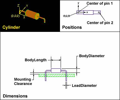
• Cylinder
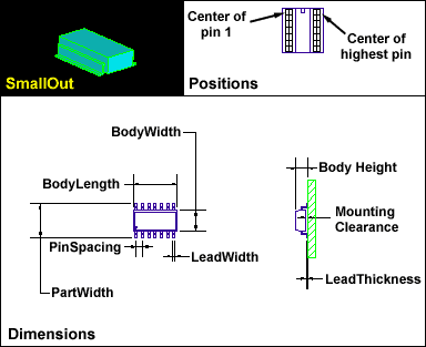
• Small outline
• Block
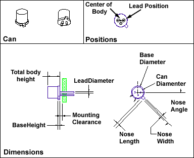
• Can
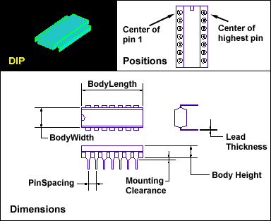
• Dip
You do not need to use any additional Creo Elements/Direct Modeling commands to create these models. However, you can use the geometry of any existing (imported or newly created) part to define the exact geometry of your new model. Optionally, you can use construction geometry to ensure accuracy.
It is recommended that you create a workplane and place the origin of your new model at (0,0) on the workplane.
The part origin (0, 0) corresponds to the equivalent origin in the ECAD interface's representation of the same part.
IDF Data Adapter (PCB I/F) automatically creates a new part structure and the model itself. The model colors are controlled by your current IDF Data Adapter (PCB I/F) configuration file.
Click PCB and then, in the Part group, click Add to add the model to a PCB assembly.

 Add to add the model to a PCB assembly.