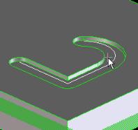
The Groove Mill function removes material along a tool path, simulating a cutting tool. You can choose between several cutting tool profiles.
To define the tool path, you create 2D geometry in a workplane. The tool cuts along the path perpendicular to the workplane.
The profile requirements of other machining commands do not apply to the Groove Mill path. For example, a Groove Mill path does not have to be closed, and T-shapes are allowed.
Corners (including start and end corners) are handled exactly like cutting tools. That means the groove has cylindrical faces at the tool path's start and end points. Where the path changes direction, the groove gets a sharp edge on the inner side of the curve, and a cylindrical face on the outer side.
Direction changes at angles below 5 degrees are not supported.
Groove Mill processes the path sections one by one. If it fails for a section, you have to confirm whether you want to keep the successfully created sections.
The following types of cutting tools are available:
Cylinder
The Cylinder tool cuts a rectangular groove.
• D, the tool diameter, defines the width of the groove.
• L, the tool length, defines the depth of the groove.
Tapered Cylinder
The Tapered Cylinder tool cuts a groove with tapered sides.
• D, the tool tip diameter, defines the lower width of the groove.
• Angle, which must fall in the range of 0 to 90 degrees, defines the angle of the tapered groove's sides.
• L, the tool length, defines the depth of the groove.
Torus
The Torus tool cuts a groove with rounded bottom edges.
• D, the tool tip diameter, defines the width of the groove.
• L, the tool length, defines the depth of the groove.
• R, the tool tip's edge radius, defines the radius of the lower groove edges.
R must be smaller than L.
Sphere
The Sphere tool cuts a circular groove.
• D/2, half of the tool tip diameter, defines the radius of the groove.
• L, the tool length, defines the depth of the groove.
D/2 must be smaller than L. The command fails if the path's curvature radius is smaller than 2/D.
To groove mill a part,
1. Position a workplane on the face you want to work on.
2. Create the 2D geometry for the cutting tool path.
3. Click Mold Design and then, in the Model group, click Groove Mill. The Groove Mill dialog box opens.
4. If necessary, click Part and specify a different part.
5. If necessary, click Workplane and specify a different workplane.
6. If necessary, change Direction. You can cut the groove either on the positive (w+) or negative (w-) side of the workplane.
7. Under Parameters, choose the Tool Type. Your options are Cylinder, Tapered Cylinder, Sphere, or Torus. For the different parameters of each tool profile see the tool table above.
8. To keep the workplane and the tool path, leave the options Keep WP and Keep Prof. switched on.
 Groove Mill. The Groove Mill dialog box opens.